
Installation Guide

6 Electrical Connection SMA America, LLC
34 SB3-5TLUS22-IA-en-16 Installation Manual
6.2 Overview of the Connection Area
6.2.1 Connection Area of the Inverter
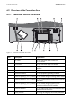
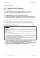
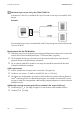
Figure11: Connection area inside the inverter
Item Description Explanation
A DC cable For the connection of the inverter and
DC Disconnect
B Pin connector For the connection of the SPS module
C Pin connector For the connection of the communication
interface
D Terminal For the AC cables
E Ground connection For the equipment grounding conductor
F Enclosure opening (
3
⁄
4
in. (19 mm)) For the conduit fitting for inserting the AC cables
G Enclosure opening (
3
⁄
4
in. (19 mm)) For the conduit fitting for insertion of the optional
data cable
H Enclosure opening (
3
⁄
4
in. (19 mm)) For the conduit fitting for insertion of the
connection cable of the SPS module
I Enclosure opening For the cable gland used to insert the connection
cable for the fan retrofit kit*
K Rotary switches For setting the language and country standard