PV Inverter SUNNY BOY 3000TL-US / 3800TL-US / 4000TL-US / 5000TL-US / 6000TL-US / 7000TL-US / 7700TL-US Installation Manual SB3-5TLUS22-IA-en-16 | Version 1.
SMA America, LLC Copyright © 2014 SMA America, LLC. All rights reserved. No part of this document may be reproduced, stored in a retrieval system, or transmitted, in any form or by any means, electronic, mechanical, photographic, magnetic or otherwise, without the prior written permission of SMA America, LLC. Neither SMA America, LLC nor SMA Solar Technology Canada Inc.
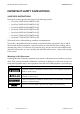
IMPORTANT SAFETY INSTRUCTIONS SMA America, LLC IMPORTANT SAFETY INSTRUCTIONS SAVE THESE INSTRUCTIONS This manual contains important instructions for the following products: • Sunny Boy 3000TL-US (SB 3000TL-US-22) • Sunny Boy 3800TL-US (SB 3800TL-US-22) • Sunny Boy 4000TL-US (SB 4000TL-US-22) • Sunny Boy 5000TL-US (SB 5000TL-US-22) • Sunny Boy 6000TL-US (SB 6000TL-US-22) • Sunny Boy 7000TL-US (SB 7000TL-US-22) • Sunny Boy 7700TL-US (SB 7700TL-US-22) This manual must be followed during installation and main
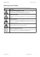
SMA America, LLC Warnings on this Product Warnings on this Product The following symbols are used as product markings with the following meanings. Symbol Description Warning regarding dangerous voltage The product works with high voltages. All work on the product must only be performed as described in the documentation of the product. Beware of hot surface The product can become hot during operation. Do not touch the product during operation.
General Warnings SMA America, LLC General Warnings General Warnings All electrical installations must be made in accordance with the local and National Electrical Code® ANSI/NFPA 70 or the Canadian Electrical Code® CSA C22.1. This document does not and is not intended to replace any local, state, provincial, federal or national laws, regulation or codes applicable to the installation and use of the product, including without limitation applicable electrical safety codes.
SMA America, LLC Table of Contents Table of Contents 1 Information on this Document. . . . . . . . . . . . . . . . . . . . . . . . . . 10 2 Safety . . . . . . . . . . . . . . . . . . . . . . . . . . . . . . . . . . . . . . . . . . . . . 12 2.1 Intended Use . . . . . . . . . . . . . . . . . . . . . . . . . . . . . . . . . . . . . . . . . . . 12 2.2 Skills of Qualified Persons . . . . . . . . . . . . . . . . . . . . . . . . . . . . . . . . . 12 2.3 Safety Precautions . . . . . . . . . . . . . . . . . . . .
Table of Contents SMA America, LLC 6.2 Overview of the Connection Area . . . . . . . . . . . . . . . . . . . . . . . . . . . 34 6.2.1 Connection Area of the Inverter. . . . . . . . . . . . . . . . . . . . . . . . . . . . 34 6.2.2 Connection Area of the DC Disconnect . . . . . . . . . . . . . . . . . . . . . . 35 6.3 AC Connection . . . . . . . . . . . . . . . . . . . . . . . . . . . . . . . . . . . . . . . . . 36 6.3.1 Conditions for the AC Connection . . . . . . . . . . . . . . . . . . . . . . . . . .
SMA America, LLC Table of Contents 11.4 Cleaning the Fan . . . . . . . . . . . . . . . . . . . . . . . . . . . . . . . . . . . . . . . . 71 11.4.1 Sunny Boy 3000/3800/4000/5000/6000TL-US . . . . . . . . . . . . 71 11.4.2 Sunny Boy 7000/7700TL-US . . . . . . . . . . . . . . . . . . . . . . . . . . . . . 73 11.5 Checking the PV System for Ground Faults . . . . . . . . . . . . . . . . . . . . 74 11.6 Replacing DC Varistors . . . . . . . . . . . . . . . . . . . . . . . . . . . . . . . . . . . 76 11.
1 Information on this Document SMA America, LLC 1 Information on this Document Validity This document is valid for the following device types as of firmware version HP V02.05.00.R, KP V02.50.55.
SMA America, LLC 1 Information on this Document Nomenclature Complete designation Designation in this document SMA America Production, LLC SMA SMA Solar Technology Canada Inc.
2 Safety SMA America, LLC 2 Safety 2.1 Intended Use The Sunny Boy is a transformerless PV inverter which converts the direct current of a PV array into grid-compliant alternating current and feeds it into the utility grid. The inverter can be installed in the following grid configurations: • 208Y/120 VAC Wye • 120/240 VAC Split phase The inverter is transformerless and has no galvanic isolation. Therefore, the inverter may only be operated with ungrounded PV arrays.
SMA America, LLC 2 Safety 2.3 Safety Precautions Danger to life from electric shock due to high voltages in the inverter High voltages that can cause fatal electric shocks are present in the live components of the inverter. • All work on the inverter may only be carried out by qualified persons. • Prior to performing any work on the inverter, disconnect the inverter on the AC and DC sides (see Section 10 "Disconnecting the Inverter from Voltage Sources", page 55).
3 Scope of Delivery SMA America, LLC 3 Scope of Delivery Check the scope of delivery for completeness and any externally visible damage. Contact your distributor if the scope of delivery is incomplete or damaged.
SMA America, LLC 4 Product Description 4 Product Description 4.1 Sunny Boy The Sunny Boy is a transformerless PV inverter which converts the direct current of a PV array into grid-compliant alternating current and feeds it into the utility grid.
4 Product Description SMA America, LLC The Sunny Boy is a multi-string inverter that has two input areas, A and B, each with its own MPP tracker. This continually determines the maximum power point and controls the voltage on the PV modules accordingly. The two separate MPP trackers make it possible to connect different PV strings to input areas A and B. The PV strings may vary in the number of PV modules, their orientation to the sun and shading.
SMA America, LLC 4 Product Description 4.2 DC Disconnect The DC Disconnect is a DC load-break switch which safely disconnects the PV array from the inverter.
4 Product Description SMA America, LLC 4.3 Type Labels 4.3.1 Sunny Boy The type label provides a unique identification of the inverter. The type label is located on the right-hand side of the enclosure.
SMA America, LLC 4 Product Description 4.3.2 DC Disconnect The type label provides a unique identification of the DC Disconnect. The type label is located on the right-hand side of the enclosure. Figure 5: Layout of the type label Item Description Explanation A ‒ Product name B Item No. DC Disconnect device type C Date of manufacture DC Disconnect manufacture date (month/year) of the D Device-specific characteristics ‒ E Serial No.
4 Product Description SMA America, LLC 4.3.3 Symbols on the Type Labels Symbol Description Explanation Danger to life due to high voltages The product operates at high voltages. All work on the inverter may only be carried out by qualified persons. Risk of burns due to hot surfaces The product can become hot during operation. Avoid contact during operation. Allow the product to cool down sufficiently before carrying out any work. Wear personal protective equipment such as safety gloves.
SMA America, LLC 4 Product Description 4.4 Display The display shows the current operating data of the inverter (e.g. current power, daily energy, total energy) as well as events or error messages. The power and energy are displayed as bars in the diagram.
4 Product Description SMA America, LLC Position Description Explanation K Event number relating to the PV array Event number of errors relating to the PV array L Text line Displays an event message or error message M Power and yield curve Displays the power curve of the last 16 feed-in hours or the energy yields of the last 16 days • In order to switch between the displays, tap once on the enclosure lid.
SMA America, LLC Symbol 4 Product Description Description Explanation Grid relay Grid relay closed: indicates that the inverter is feeding into the utility grid Grid relay open: indicates that the inverter is disconnected from the utility grid Utility grid ‒ 4.5 Communication Interface The inverter can be fitted with a communication interface (e.g. RS485 or Speedwire with Webconnect function).
4 Product Description SMA America, LLC 4.8 Arc-Fault Circuit Interrupter (AFCI) In accordance with the National Electrical Code®, Article 690.11, the inverter has a system for the recognition of electric arc detection and interruption. An electric arc with a power of 300 W or greater must be interrupted by the AFCI within the time specified by UL 1699B. A tripped AFCI can only be reset manually.
SMA America, LLC 5 Mounting 5 Mounting 5.1 Selecting the Mounting Location Requirements for the mounting location: Danger to life due to fire or explosion Despite careful construction, electrical devices can cause fires. • Do not mount the inverter in areas where highly flammable materials are stored. • Do not mount the inverter in areas having a potentially explosive atmosphere The inverter can become hot during operation Touching the enclosure can result in burn injuries.
5 Mounting SMA America, LLC Dimensions for mounting: Figure 7: 26 Wall mounting bracket dimensions SB3-5TLUS22-IA-en-16 Installation Manual
SMA America, LLC 5 Mounting Recommended Clearances Figure 8: Recommended clearances • To ensure optimal operation, maintain recommended clearances to walls, other inverters or objects. This will prevent the inverter from reducing its power due to high temperatures. • If the inverter is mounted outdoors, the clearance between the DC Disconnect and the floor must be 3 ft. (914 mm). This prevents the ingress of splashing water into the DC Disconnect. • Do not place or hang any objects on the inverter.
5 Mounting SMA America, LLC Observe the permitted mounting position: Figure 9: Permitted and prohibited mounting positions • Mount the inverter in a permitted mounting position with the display at eye level. This ensures that there can be no ingress of moisture into the inverter and that you can read display messages and LED signals without any difficulty. 5.
SMA America, LLC 5 Mounting 2. Align the wall mounting bracket horizontally at the mounting location. 3. Danger to life due to electric shock or explosion if you drill into supply lines There may be gas pipes or electric cables behind the mounting points which could be damaged when drilling the holes for the wall mounting bracket. • Make sure that there are no supply lines behind the mounting points. 4.
5 Mounting SMA America, LLC 5.3 Mounting the Inverter and DC Disconnect 1. Risk of injury when lifting the inverter, or if it is dropped The inverter is heavy (see Section 13 "Technical Data", page 82). Risk of injury exists due to incorrect lifting and due to the inverter falling during transport or when hanging in the wall mounting bracket. • Lift and transport the inverter horizontally in the mounting position. Use the recessed grips on the sides for this. 2.
SMA America, LLC 5 Mounting 6. Place the DC Disconnect into the retainer from the front. 7. Attach the DC Disconnect to the ground connection on the inverter using the grounding bracket. Use the M6x8 screw included in the delivery, the corresponding conical spring washer and an Allen key (AF 5) (torque: 53 in-lbs. (6 Nm)). When doing so, ensure that the holes in the lateral brackets of the DC Disconnect are flush with the holes in the retainer. 8.
5 Mounting SMA America, LLC 5.4 Attaching the Anti-Theft Device You can protect the inverter from theft by installing a padlock. The padlock secures the inverter to the wall mounting bracket. The padlock must meet the following requirements: ☐ The material should be rust-proof. ☐ The lock shackle should be hardened. ☐ The lock cylinder should be secured. ☐ If mounted outdoors, the padlock should be weather-proof. Figure 10: Dimensions of the padlock as anti-theft device Item Dimensions A 6 mm (0.
SMA America, LLC 6 Electrical Connection 6 Electrical Connection 6.1 Safety during Electrical Connection Danger to life from electric shock due to high voltages High voltages are present in the DC cables and later during operation in the conductive components of the inverter. These can cause fatal electric shocks. • Before working on the inverter, always disconnect the inverter from all voltage sources as described in Section 10. • Do not open the upper enclosure lid.
6 Electrical Connection SMA America, LLC 6.2 Overview of the Connection Area 6.2.1 Connection Area of the Inverter Figure 11: Connection area inside the inverter Item Description Explanation A DC cable For the connection of the inverter and DC Disconnect B Pin connector For the connection of the SPS module C Pin connector For the connection of the communication interface D Terminal For the AC cables E Ground connection (3⁄4 (3⁄4 For the equipment grounding conductor in.
SMA America, LLC 6 Electrical Connection Item Description Explanation L Slot For SD card M Retainer For the retrofit fan* N Ground connection For the DC Disconnect grounding bracket *The Sunny Boy 6000TL-US, 7000TL-US and 7700TL-US are equipped with a fan as standard. 6.2.
6 Electrical Connection SMA America, LLC 6.3 AC Connection 6.3.1 Conditions for the AC Connection Cable requirements: ☐ Conductor cross-section L1, L2, N: 12 AWG to 6 AWG (3.3 mm² to 13.3 mm²) ☐ Conductor cross-section equipment grounding conductor: 12 AWG (3.3 mm²) ☐ Isolation stripping length: 1⁄2 in. (12 mm) ☐ Solid or stranded wire of copper with no more than 19 single wires ☐ The cables must be designed in accordance with local directives and the National Electrical Code®.
SMA America, LLC 6 Electrical Connection 6.3.2 Connecting the Inverter to the Utility Grid Requirements: ☐ The country data set and the display language must be correctly set (see Section 7.1 "Making Settings via the Rotary Switches", page 47). ☐ The connection requirements of the grid operator must be met. ☐ The line voltage must be within the permissible range. The exact operating range of the inverter is specified in the operating parameters. 1.
6 Electrical Connection SMA America, LLC 8. Danger of crushing when safety levers snap shut The safety levers close by snapping down fast and hard. • Only press the safety levers on the terminals down with your thumb. Do not grasp the entire AC connecting terminal plate and do not place your fingers under the safety levers. 9. Ensure that the conductors are securely in place in the terminals. 10. Loosen the cheese-head screw on the ground connection using an Allen key (AF 5). 11.
SMA America, LLC 6 Electrical Connection 6.4 DC Connection 6.4.1 Safety during DC Connection Danger to life due to high voltages on DC conductors Risk of death or serious injury due to electric shock from touching a DC conductor. • Do not touch the DC conductors. Danger of electric arcs due to reversed-pole DC conductors Dangerous electric arcs can form when the DC conductors are connected to the incorrect poles on the inverter. • Only make the DC connection as described in this document.
6 Electrical Connection SMA America, LLC Maximum input current Sunny Boy 7000/7700TL-US A maximum of 18 A DC is possible per DC input. The total current may not exceed 30 A DC though. Example: If the maximum input current is exceeded due to the PV array design, the inverter limits the total current to 30 A DC.
SMA America, LLC 6 Electrical Connection 6.4.3 Connecting the PV Array Destruction of the inverter due to overvoltage If the open-circuit voltage of the PV modules exceeds the maximum system voltage of the inverter, the inverter can be destroyed by overvoltage. • Ensure that the open-circuit voltage of the PV modules does not exceed the maximum input voltage of the inverter. • Otherwise, do not connect strings to the inverter; check the design of the PV system. 1.
6 Electrical Connection SMA America, LLC 7. Damage to the DC Disconnect due to enlarged knockouts Enlarged knockouts enable moisture to penetrate the DC Disconnect which could damage electronic components in the DC Disconnect. • Do not enlarge the knockouts. 8. Connect the connection cable of the inverter in the DC Disconnect. Use a flat-blade screwdriver (blade width 5 mm) for this (torque 15 in-lb. (1.7 Nm)). • Insert the red cable into the RD screw terminal and tighten the terminal.
SMA America, LLC 6 Electrical Connection 15. If there is another string for input A, connect it in the same way to the terminal blocks for input A. 16. Connect the first string for input B to the terminal blocks for input B. Use a flat-blade screwdriver (blade width: 5 mm) for this (torque: 15 in-lb. (1.7 Nm)). • Insert the cable DC+ into the screw terminal + and tighten the terminal. Ensure the correct polarity when doing so. • Insert the cable DC − into the screw terminal − and tighten the terminal.
6 Electrical Connection SMA America, LLC 6.5 Connecting the Secure Power Supply Module Circuit Diagram Additionally required mounting material (not included in the scope of delivery): ☐ Outlet for secure power supply operation ☐ Switch to activate the secure power outlet that is designed for at least 120 V (AC) and 10 A ☐ 1 conduit fitting (3⁄4 in. (19 mm)), rain-tight or for wet locations when installed outdoors ☐ 1 conduit (3⁄4 in.
SMA America, LLC 6 Electrical Connection Procedure 1. If the inverter is in operation, disconnect it (see Section 10). 2. Loosen the screw on the display and flip the display up until it clicks into place. 3. Remove the filler plugs from the enclosure opening in the inverter. 4. Install the conduit with conduit fitting in the enclosure opening. 5. Feed the cable through the conduit to the terminals on the SPS module. 6. Strip 11⁄32 in. (9 mm) off the conductor insulation. 7.
6 Electrical Connection SMA America, LLC 8. Ensure that the grounding cable of the module is connected to the ground connection in the inverter. 9. Secure the conduit fitting from the inside using the counter nut. 10. Connect the insulated conductors that are connected to the three-colored terminals of the SPS module to the outlet. 11. Connect the insulated conductors that are connected to the black terminals of the SPS module to the switch. 12.
SMA America, LLC 7 Commissioning 7 Commissioning 7.1 Making Settings via the Rotary Switches 7.1.1 Overview of the Rotary Switches The inverter can be configured for different countries and for use in backup and off-grid systems via two rotary switches. The rotary switches can also be used to change the display language. By default, the inverter is set to a specific country data set.
7 Commissioning SMA America, LLC Possible Settings of the Rotary Switches Here, you will find a list of possible rotary switch positions and which country data sets and display languages are represented by each position. Each country data set contains various operating parameters, which can be individually set according to each country data set. The operating parameters can be read out using a communication product.
SMA America, LLC 7 Commissioning Rotary switch A position Rotary switch B position Country data set Display language D 2 Island mode 60 Hz French D 3 Island mode 60 Hz Spanish D 4 Island mode 60 Hz Italian D 5 Island mode 60 Hz Greek D 6 Island mode 60 Hz Czech E 0 Island mode 50 Hz English E 1 Island mode 50 Hz German E 2 Island mode 50 Hz French E 3 Island mode 50 Hz Spanish E 4 Island mode 50 Hz Italian E 5 Island mode 50 Hz Greek E 6 Island mode 50 Hz
7 Commissioning SMA America, LLC 7.1.3 Changing the Display Language You can change the display language independent of the country data set. This ensures that the country data set remains unchanged. Hint: If you simply remove the jumper, the display language automatically changes to English. 1. If the inverter is in operation, disconnect it (see Section 10). 2. Set the rotary switch A to 0 using a slotted screwdriver (blade width: 2.5 mm). This ensures that the country data set remains unchanged. 3.
SMA America, LLC 7 Commissioning 7.2 Commissioning the Inverter Requirements: ☐ AC overcurrent protection and AC disconnecting unit must be correctly designed. ☐ The inverter must be correctly mounted and closed. ☐ The DC Disconnect must be correctly mounted and closed. ☐ All cables must be correctly connected. 1. Place the lower enclosure lid with the 6 screws onto the enclosure and tighten them using an Allen key (AF 3) in the order 1 to 6 (torque: 18 in-lbs. (2.0 Nm). 2.
8 Configuration SMA America, LLC 8 Configuration 8.1 Changing the Country Data Set Using a Communication Product By default, the inverter is set to a specific country data set. You can see which country data set was set by default at the factory on the type label and the supplementary sheet with the default settings provided.
SMA America, LLC 9 Display and LEDs 9 Display and LEDs 9.1 Switching On the Display By tapping on the enclosure lid once you can operate the display as follows: • Switch on the display • Switch through the text line display • Switch between the power curve of the last 16 feed-in hours and the energy yields of the last 16 days 9.2 Calling Up Messages of the Start Phase If you double tap on the enclosure lid, the display messages of the start phase are repeated.
9 Display and LEDs SMA America, LLC 9.3 LED Signals The LEDs indicate the operating state of the inverter. LED Status Green is glowing Explanation Operation If an event occurs, the event message is shown in the display (see Section 11.1). Red is flashing Conditions for connection to the grid are not fulfilled. is flashing quickly The inverter is performing an update. is glowing Error The display shows the error message and event number (see Section 11.2).
SMA America, LLC 10 Disconnecting the Inverter from Voltage Sources 10 Disconnecting the Inverter from Voltage Sources Danger to life due to high voltages in the inverter Death or serious injury due to electric shock. • Only open the inverter in the order described here. • Before performing any tasks, wait five minutes until the residual voltage has been drained from the components.
10 Disconnecting the Inverter from Voltage Sources SMA America, LLC 6. Damage to the inverter due to electrostatic discharge The internal components of the inverter can be irreparably damaged by electrostatic discharge. • Ground yourself before touching any components. 7. Ensure that no voltage is present on the AC connecting terminal plate using a suitable measuring device. Insert the test probe in each round opening of the terminal: • Ensure that no voltage is present between L1 and N.
SMA America, LLC 10 Disconnecting the Inverter from Voltage Sources • Ensure that no voltage is present between L2 and the equipment grounding conductor. 10.1 Disconnecting the DC Disconnect from Voltage Sources 1. Turn the rotary switch of the DC Disconnect to Off. 2. Wait until the LEDs and inverter display switch off. 3. Loosen the screw on the lower side of the DC Disconnect using an Allen key (AF 4) and remove the lid of the DC Disconnect. 4.
10 Disconnecting the Inverter from Voltage Sources SMA America, LLC 6. Danger to life due to electric shock when touching the DC conductors and DC terminals High voltages are present in the DC cables and DC terminals. • Before performing any tasks, wait five minutes until the residual voltage has been drained. • Do not touch the DC conductors and DC terminals. 7. Ensure that no voltage is present on the DC terminals using a suitable measuring device.
SMA America, LLC 11 Troubleshooting 11 Troubleshooting 11.1 Event Messages Display message Cause AFCI self-test successful The inverter has successfully performed the arc fault detection self-test. Backup mode on The inverter is operating in grid parallel operation with adjusted grid monitoring. Grid guard code valid The SMA Grid Guard code entered is valid. Protected parameters have now been unblocked and you can adjust the parameters.
11 Troubleshooting SMA America, LLC 11.2 Error Messages Event number Display message Cause and corrective measures 101 to 103 Grid fault The line voltage or grid impedance at the connection point of the inverter is too high. The inverter has disconnected from the utility grid. Corrective measures: • Check whether the line voltage at the connection point of the inverter is permanently in the permissible range.
SMA America, LLC 11 Troubleshooting Event number Display message Cause and corrective measures 301 Grid fault The 10-minute average line voltage is no longer within the permissible range. The line voltage or grid impedance at the connection point is too high. The inverter disconnects from the utility grid to comply with the power quality. Corrective measures: • Check whether the line voltage at the connection point of the inverter is permanently in the permissible range.
11 Troubleshooting SMA America, LLC Event number Display message Cause and corrective measures 601 Grid fault The inverter has detected an excessively high proportion of direct current in the line current. Corrective measures: • Check the grid connection for direct current. If this message is displayed frequently, contact the grid operator and check whether it is possible to raise the limiting value for monitoring on the inverter. 701 Frq.
SMA America, LLC 11 Troubleshooting Event number Display message Cause and corrective measures 1501 Reconnection fault grid The changed country data set or the value of a parameter you have set does not correspond to the local requirements. The inverter cannot connect to the utility grid. Corrective measures: • Ensure that the country data set has been configured correctly. Check the setting of the rotary switches A and B or select the parameter Set country standard and check the value.
11 Troubleshooting SMA America, LLC Event number Display message Cause and corrective measures 3501 Insulation resist. The inverter has detected a ground fault in the PV array. Check generator Corrective measures: • Check the PV system for ground faults (see Section 11.5). 3601 High discharge curr. Check generator The leakage current from the inverter and the PV array is too high. A ground fault, a residual current or a malfunction is present.
SMA America, LLC 11 Troubleshooting Event number Display message Cause and corrective measures 6001 to 6009 Self diagnosis The cause must be determined by the SMA Service Line. Interference device Corrective measures: • Contact the SMA Service Line. 6101 to 6112 Self diagnosis Interference device The cause must be determined by the SMA Service Line. Corrective measures: • Contact the SMA Service Line. 6202 Self diagnosis Interference device The cause must be determined by the SMA Service Line.
11 Troubleshooting SMA America, LLC Event number Display message Cause and corrective measures 6701 to 6702 Comm. disturbed A fault has occurred in the internal communication of the inverter. The inverter continues feeding power into the grid. Corrective measures: If this event occurs frequently: • Contact the SMA Service Line. 6801 to 6802 Self diagnosis Inverter input A is defective. Input A defective Corrective measures: • Contact the SMA Service Line.
SMA America, LLC 11 Troubleshooting Event number Display message Cause and corrective measures 7105 Param. setting failed Parameters cannot be set via the SD card. The inverter continues feeding power into the grid. Corrective measures: • Check the parameters for valid values. • Ensure change rights via SMA Grid Guard code. 7106 Update file defect. The update file is defective. The update failed. The inverter continues feeding power into the grid. Corrective measures: • Re-format the SD card.
11 Troubleshooting SMA America, LLC Event number Display message Cause and corrective measures 7311 Update language table Internal device fault, the inverter continues failed feeding power into the grid. Corrective measures: • Re-try update. • If this error occurs again, contact the SMA Service Line. 7316 Update Speedwire module failed Internal device fault, the inverter continues feeding power into the grid. Corrective measures: • Re-try update.
SMA America, LLC 11 Troubleshooting Event number Display message Cause and corrective measures 8001 Derating occurred The inverter has reduced its power output for more than ten minutes due to excessive temperature. Corrective measures: • If this message is frequently displayed, clean the cooling fins and air ducts (see Section 11.3 "Cleaning the Inverter", page 71). • Ensure that the inverter has sufficient ventilation. 8101 to 8104 Comm.
11 Troubleshooting SMA America, LLC Event number Display message Cause and corrective measures 8801 to 8803 No display This error message can have 3 causes but the inverter continues to feed into the utility grid. The ambient temperature is lower than ‒13°F (‒25°C). The display switched off for protection. The inverter cannot identify the display type. No display is connected to the inverter or the connection is defective.
SMA America, LLC 11 Troubleshooting Event number Display message Cause and corrective measures 9005 Changing grid param. This error can have the following causes: not possible • The selected rotary switch setting for the Ensure DC supply country configuration is not programmed. • The parameters to be changed are protected. • The DC voltage at the DC input is not sufficient to run the main CPU. Corrective measures: • Check the settings of the rotary switches (see Section 7.1.
11 Troubleshooting SMA America, LLC 4. Loosen the screw on the display and flip the display up until it clicks into place. 5. Push both locking tabs of the fan casing towards the fan and remove the fan along with the fan casing. 6. Push the fan out of the fan guard from the rear side. Cleaning the Fan 7. Remove the fan and clean it with a soft brush, a paint brush or a cloth and water. Clean the fan guard as well. Damage to the fan through use of compressed air • Do not use compressed air to clean it.
SMA America, LLC 11 Troubleshooting 9. Insert the fan with fan casing into the enclosure opening. The arrow on the fan casing must point towards the display. 10. Hook the locking tabs on the right-hand side of the fan casing underneath the wall of the enclosure and press the fan with fan casing into the enclosure opening. ☑ The left-hand locking tabs snap into place. 11. Flip the display down and fasten the screw hand-tight. 12.
11 Troubleshooting SMA America, LLC Cleaning the Fan 4. Remove the fan and clean it with a soft brush, a paint brush or a cloth and water. Clean the fan guard as well. Damage to the fan through use of compressed air • Do not use compressed air to clean it. This could damage the fan. Inserting the Fan Correct airflow direction 5. The arrow and type label on the fan must point upwards before installation. 6. Slide the fan into the fan guard from the right-hand side. ☑ The fan snaps audibly into place.
SMA America, LLC 11 Troubleshooting Danger to life due to electric shock In the event of a ground fault, high voltages can be present in the PV module construction. • Only touch the cables of the PV modules on their insulation. • Do not connect DC cables with ground faults to the inverter. Proceed as follows to check each string in the PV system for ground faults. 1. Disconnect the inverter from any voltage sources (see Section 10). 2.
11 Troubleshooting SMA America, LLC 11.6 Replacing DC Varistors In regions where electrical storms or other DC overvoltages frequently occur, the DC varistors lose their functionality if the PV system is not equipped with additional overvoltage protection. In such cases, SMA recommends replacing DC varistors with new ones after an operating period of 10 years in order to ensure that the functionality of the DC varistors remains at a constant level.
SMA America, LLC 11 Troubleshooting 5. Ensure that the wires of the varistors are secure in the terminal. 6. Remove the insertion tool from the contacts of the connecting terminal plate. 7. Push the DC Disconnect lid diagonally under the upper edge of the enclosure and press the lid down. The lid must be flush with the enclosure edge. 8. Tighten the lid of the DC Disconnect using an Allen key (AF 4) and the corresponding screw and conical spring washer (torque : 44 in-lb. (5 Nm)). 9.
11 Troubleshooting SMA America, LLC 11.7 The Message "Electr. arc detected" is displayed ✖ An electric arc occurred in the PV system. ✖ The red LED is permanently lit. ✖ The AFCI has tripped and the inverter is in permanent shutdown. Danger of fire from electric arc • Only test the AFCI for false tripping in the order described below. • Do not deactivate the AFCI permanently. 1. Disconnect the inverter from voltage sources (see Section 10). 2.
SMA America, LLC 11 Troubleshooting ☑ If the AFCI self-test is successful, the green LED is lit and the display shows the device type, the firmware version, the device names, the country data set and display language. If communication is Speedwire, then the status and the versions of the communication assemblies will also be displayed also after the device names. The inverter feeds into the grid.
12 Decommissioning SMA America, LLC 12 Decommissioning 12.1 Disassembling the Inverter 1. Disconnect the inverter from any voltage sources (see Section 10). 2. Disconnect the DC Disconnect from voltage sources (see Section 10.1). 3. Remove the AC output cable from the inverter. 4. If the SPS module is connected, remove the output cable from the inverter. 5. If a data cable is connected, remove the data cable from the inverter. 6.
SMA America, LLC 12 Decommissioning 13. Tighten the lid of the DC Disconnect using an Allen key (AF 4) and the corresponding screw and conical spring washer (torque : 44 in-lb. (5 Nm)). 14. If the inverter is protected against theft, open the padlock and remove it. 15. Risk of injury when lifting the inverter, or if it is dropped The inverter is heavy (see Section 13 "Technical Data", page 82).
13 Technical Data SMA America, LLC 13 Technical Data 13.1 DC/AC 13.1.
SMA America, LLC 13 Technical Data Efficiency Maximum efficiency, ηmax CEC efficiency, ηCEC at 208 V AC nominal CEC efficiency, ηCEC at 240 V AC nominal 97.6% 96.5% 96.5% 13.1.
13 Technical Data Connection conductor Output connections SMA America, LLC 2 L1, L2, N, PE Efficiency Maximum efficiency, ηmax CEC efficiency, ηCEC at 208 V AC nominal CEC efficiency, ηCEC at 240 V AC nominal 97.5% 96.5% 97.0% 13.1.
SMA America, LLC Power factor at rated power Connection conductor Output connections 13 Technical Data 1 2 L1, L2, N, PE Efficiency Maximum efficiency, ηmax CEC efficiency, ηCEC at 208 V AC nominal CEC efficiency, ηCEC at 240 V AC nominal 97.5% 96.5% 97.0% 13.1.
13 Technical Data Total harmonic distortion Nominal AC frequency AC frequency range at 60 Hz nominal Power factor at rated power Connection conductor Output connections SMA America, LLC ≤ 4% 60 Hz 59.3 Hz to 60.5 Hz 1 2 L1, L2, N, PE Efficiency Maximum efficiency, ηmax CEC efficiency, ηCEC at 208 V AC nominal CEC efficiency, ηCEC at 240 V AC nominal 97.6% 96.5% 97.0% 13.1.
SMA America, LLC Nominal AC current at 240 V Maximum output current Maximum overcurrent protection Total harmonic distortion Nominal AC frequency AC frequency range at 60 Hz nominal Power factor at rated power Connection conductor Output connections 13 Technical Data 25 A 25,2 A 40 A ≤ 4% 60 Hz 59.3 Hz to 60.5 Hz 1 2 L1, L2, N, PE Efficiency Maximum efficiency, ηmax CEC efficiency, ηCEC at 208 V AC nominal CEC efficiency, ηCEC at 240 V AC nominal 97.4% 96.5% 97.0% 13.1.
13 Technical Data Nominal AC voltage AC voltage range at 208 V nominal AC voltage range at 240 V nominal Nominal AC current at 208 V Nominal AC current at 240 V Maximum output current Maximum overcurrent protection Total harmonic distortion Nominal AC frequency AC frequency range at 60 Hz nominal Power factor at rated power Connection conductor Output connections SMA America, LLC 208 V / 240 V 183 V to 229 V 211 V to 264 V 29.2 A 29.2 A 29.2 A 40 A ≤ 4% 60 Hz 59.3 Hz to 60.
SMA America, LLC 13 Technical Data AC Output Rated power at 208 V, 60 Hz Rated power at 240 V, 60 Hz Maximum apparent power at 208 V, 60 Hz Maximum apparent power at 240 V, 60 Hz Nominal AC voltage AC voltage range at 208 V nominal AC voltage range at 240 V nominal Nominal AC current at 208 V Nominal AC current at 240 V Maximum output current Maximum overcurrent protection Total harmonic distortion Nominal AC frequency AC frequency range at 60 Hz nominal Power factor at rated power Connection conductor Ou
13 Technical Data SMA America, LLC 13.
SMA America, LLC 13 Technical Data 13.4 DC Disconnect Maximum rated switching current per string input Maximum switching voltage Degree of protection 20 A 600 V NEMA 3R 13.5 Climatic Conditions According to IEC 60721-3-4, installation type C, class 4K4H Extended temperature range Extended humidity range Extended air pressure range − 40°F to +140°F ( − 40°C to +60°C) 0% to 100% 79.
13 Technical Data SMA America, LLC 13.7 Torques Lower inverter lid screws DC Disconnect lid screw Screws of the DC Disconnect retainer on the inverter wall mounting bracket Screws of the DC Disconnect on the retainer Ground connection in the inverter Grounding screw in the grounding bracket of the DC Disconnect on the inverter DC grounding terminal in the DC disconnect DC terminals for the PV modules DC terminal for the inverter DC cable in the DC Disconnect 18 in.-lbs. (2.0 Nm) 44 in.-lbs. (5.
SMA America, LLC 14 Accessories 14 Accessories You will find relevant accessories and spare parts for your product in the following overview. If required, these can be ordered from SMA or your distributor. Description Brief description SMA order number DC replacement varistors Set with 4 varistors incl.
15 Compliance Information SMA America, LLC 15 Compliance Information FCC Compliance This device complies with Part 15 of the FCC Rules. Operation is subject to the following conditions: 1. This device may not cause harmful interference, and 2. This device must accept any interference received, including interference that may cause undesired operation. NOTE: This equipment has been tested and found to comply with the limits for a Class B digital device, pursuant to Part 15 of the FCC Rules.
SMA America, LLC 16 Contact 16 Contact If you have technical problems concerning our products, contact the SMA Service Line.
SMA Solar Technology www.SMA-Solar.com SMA America, LLC www.SMA-America.