
SI4548-US-10 Manual
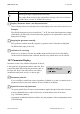

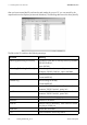

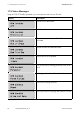
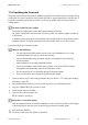
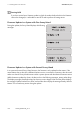
Table Of Contents
- 1 Information on this Manual
- 2 Sunny Island 4548-US/6048-US
- 3 Safety Precautions
- 4 Assembly
- 5 Opening and Closing
- 6 Electrical Connection
- 7 Control Elements
- 8 Initial Start-Up
- 9 Switching On and Off
- 10 Operation
- 11 Archiving Data on an SD Card
- 12 Additional Functions
- 12.1 Load Shedding
- 12.2 Sleep Mode
- 12.3 Time-Controlled Operation
- 12.4 Overload and Short-Circuit Behavior
- 12.5 Mixed Operation with Sunny Island inverters of Different Power
- 12.6 Device Faults and Autostart
- 12.7 Automatic Frequency Synchronization
- 12.8 Time-Controlled Standby
- 12.9 Behavior in the Event of a Failure in a Three-Phase System
- 13 Battery Management
- 14 Connecting External Sources
- 14.1 Generator
- 14.1.1 Parallel Connection
- 14.1.2 Generator Start Options
- 14.1.3 Generator Operation
- 14.1.4 Manual Generator Operation
- 14.1.5 Automatic Generator Operation
- 14.1.6 Limits and Power Control
- 14.1.7 Run Times
- 14.1.8 Operation Together with PV Inverters and Wind Power Inverters
- 14.1.9 Stopping the Generator
- 14.1.10 Stopping the Sunny Island
- 14.1.11 Disturbances
- 14.2 Grid
- 14.2.1 Limits of the Voltage Range and Frequency Range
- 14.2.2 Starting the Sunny Island
- 14.2.3 Operation in the Event of Grid Failure in a Grid-Tie Backup Configuration
- 14.2.4 Backup Operation and Anti-Islanding
- 14.2.5 Grid Reconnection
- 14.2.6 Grid Operation
- 14.2.7 Grid Failure
- 14.2.8 Disturbances
- 14.2.9 Limits and Power Control
- 14.2.10 Operation Together with PV Inverters and Wind Power Inverters
- 14.3 Generator and Grid
- 14.1 Generator
- 15 Relays
- 16 Multicluster Operation
- 16.1 Communication between the Sunny Island inverters
- 16.2 Initial Start-Up of the Multicluster System
- 16.3 Switching a Multicluster System On and Off
- 16.4 Generator Operation
- 16.5 Behavior with Different States of Charge
- 16.6 Testing the Multicluster Communication
- 16.7 Automatic Frequency Synchronization
- 16.8 Updating the Firmware
- 16.9 Error Handling in the Multicluster System
- 16.10 Grid Operation
- 16.11 Generator Emergency Operation
- 17 PV Inverters
- 18 Maintenance and Care
- 19 Parameter Lists
- 20 Troubleshooting
- 21 Accessories
- 22 Technical Data
- 23 Glossary
- 24 Contact

SMA America, LLC 10 Operation
Technical description SI4548_6048-US-TB_en-13 91
10.7 Parameter Display
Parameters on the Sunny Island are displayed as follows:
In the upper line, the parameter number comes first, then
a separator (hash) followed by the parameter name. In
the lower line, there is the value with the unit and the
modification mark (enter arrow) is on the far right.
Warning message is displayed (at position (H):
This symbol blinks until you have confirmed the warning or the error in the menu
"410# Failures Current" or "420# Failure History".
Display "Generator Status" and "Request Reason"
The two displays above are cyclically shown on the display as the status of the external source.
Example:
If the display changes every three seconds from "*" to "B", this means that the generator voltage
and frequency lie within the set limits and that the generator was requested as a result of the
battery state of charge.
Stopping the generator manually
If the generator has been manually stopped, no generator status information is displayed.
The field remains empty in this case.
Indications of a warning
If faults occur, the device switches into standby mode and shows the fault on the display.
The fault must be eliminated and confirmed, then the Sunny Island carries out an autostart.
Parameter/value list
If you would like to switch from a menu (regardless of whether it is a main or sub-menu) into a
parameter/value list, the menu numbers are not included on the display.
Syntax for menus and parameters
The syntax specified here for menus and parameters applies throughout the entire document.
A menu is identified by the number of the menu, the hash and the name of the menu
(e.g. 120# Battery Meters).
A parameter is labeled with the menu number, dot, the parameter number and parameter name
(120.02 BatVtg).
Symbol Meaning