
SI4548-US-10 Manual
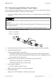
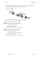


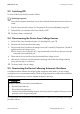


Table Of Contents
- 1 Information on this Manual
- 2 Sunny Island 4548-US/6048-US
- 3 Safety Precautions
- 4 Assembly
- 5 Opening and Closing
- 6 Electrical Connection
- 7 Control Elements
- 8 Initial Start-Up
- 9 Switching On and Off
- 10 Operation
- 11 Archiving Data on an SD Card
- 12 Additional Functions
- 12.1 Load Shedding
- 12.2 Sleep Mode
- 12.3 Time-Controlled Operation
- 12.4 Overload and Short-Circuit Behavior
- 12.5 Mixed Operation with Sunny Island inverters of Different Power
- 12.6 Device Faults and Autostart
- 12.7 Automatic Frequency Synchronization
- 12.8 Time-Controlled Standby
- 12.9 Behavior in the Event of a Failure in a Three-Phase System
- 13 Battery Management
- 14 Connecting External Sources
- 14.1 Generator
- 14.1.1 Parallel Connection
- 14.1.2 Generator Start Options
- 14.1.3 Generator Operation
- 14.1.4 Manual Generator Operation
- 14.1.5 Automatic Generator Operation
- 14.1.6 Limits and Power Control
- 14.1.7 Run Times
- 14.1.8 Operation Together with PV Inverters and Wind Power Inverters
- 14.1.9 Stopping the Generator
- 14.1.10 Stopping the Sunny Island
- 14.1.11 Disturbances
- 14.2 Grid
- 14.2.1 Limits of the Voltage Range and Frequency Range
- 14.2.2 Starting the Sunny Island
- 14.2.3 Operation in the Event of Grid Failure in a Grid-Tie Backup Configuration
- 14.2.4 Backup Operation and Anti-Islanding
- 14.2.5 Grid Reconnection
- 14.2.6 Grid Operation
- 14.2.7 Grid Failure
- 14.2.8 Disturbances
- 14.2.9 Limits and Power Control
- 14.2.10 Operation Together with PV Inverters and Wind Power Inverters
- 14.3 Generator and Grid
- 14.1 Generator
- 15 Relays
- 16 Multicluster Operation
- 16.1 Communication between the Sunny Island inverters
- 16.2 Initial Start-Up of the Multicluster System
- 16.3 Switching a Multicluster System On and Off
- 16.4 Generator Operation
- 16.5 Behavior with Different States of Charge
- 16.6 Testing the Multicluster Communication
- 16.7 Automatic Frequency Synchronization
- 16.8 Updating the Firmware
- 16.9 Error Handling in the Multicluster System
- 16.10 Grid Operation
- 16.11 Generator Emergency Operation
- 17 PV Inverters
- 18 Maintenance and Care
- 19 Parameter Lists
- 20 Troubleshooting
- 21 Accessories
- 22 Technical Data
- 23 Glossary
- 24 Contact

SMA America, LLC 8 Initial Start-Up
Technical description SI4548_6048-US-TB_en-13 71
8.3 Commissioning the Battery Current Sensor
In the event you have installed a battery current sensor in your system, you are required to synchronize
the internal offset of the device. To do this, proceed as follows:
1. Set the Sunny Island to standby mode (see Section 9.2 "Stopping the Sunny Island (Standby)",
page 74).
2. Short-circuit the battery current sensor cables.
– BatCur+ to terminal 1
– BatCur– to terminal 1
3. Enter the installer password (see Section 10.5 "Entering the Installer Password", page 86).
4. Set the following parameters:
Choose the type of battery current sensor:
– "225.01 BatCurSnsTyp" (None/50 mV/60 mV). Only after activation of the parameter
with 50 mV or 60 mV, other parameters (02, 03 and 04 in the menu "225# Battery Current
Sensor") will be shown and activated.
5. Set the nominal current of the battery current sensor (e.g. 400 A/60 mV):
– "225.02 BatCurGain60": (for a 60 mV output)
– "225.03 BatCurGain50": (for a 50 mV output)
6. Start automatic calibration:
– Set "225.04 BatCurAutoCal" to "Start".
☑ The Sunny Island conducts an automatic calibration.
7. Check the offset error:
Display value "120.06 TotBatCur" should be (close to) zero.
Entering incorrect parameters endangers operational safety. Damage to the off-grid system and its
components.
All parameter settings which could affect the operating safety of the off-grid system are protected
by the installer password.
• Only electrically qualified persons are permitted to set and adjust system parameters.