
SI4548-US-10 Manual


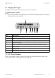


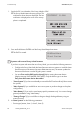


Table Of Contents
- 1 Information on this Manual
- 2 Sunny Island 4548-US/6048-US
- 3 Safety Precautions
- 4 Assembly
- 5 Opening and Closing
- 6 Electrical Connection
- 7 Control Elements
- 8 Initial Start-Up
- 9 Switching On and Off
- 10 Operation
- 11 Archiving Data on an SD Card
- 12 Additional Functions
- 12.1 Load Shedding
- 12.2 Sleep Mode
- 12.3 Time-Controlled Operation
- 12.4 Overload and Short-Circuit Behavior
- 12.5 Mixed Operation with Sunny Island inverters of Different Power
- 12.6 Device Faults and Autostart
- 12.7 Automatic Frequency Synchronization
- 12.8 Time-Controlled Standby
- 12.9 Behavior in the Event of a Failure in a Three-Phase System
- 13 Battery Management
- 14 Connecting External Sources
- 14.1 Generator
- 14.1.1 Parallel Connection
- 14.1.2 Generator Start Options
- 14.1.3 Generator Operation
- 14.1.4 Manual Generator Operation
- 14.1.5 Automatic Generator Operation
- 14.1.6 Limits and Power Control
- 14.1.7 Run Times
- 14.1.8 Operation Together with PV Inverters and Wind Power Inverters
- 14.1.9 Stopping the Generator
- 14.1.10 Stopping the Sunny Island
- 14.1.11 Disturbances
- 14.2 Grid
- 14.2.1 Limits of the Voltage Range and Frequency Range
- 14.2.2 Starting the Sunny Island
- 14.2.3 Operation in the Event of Grid Failure in a Grid-Tie Backup Configuration
- 14.2.4 Backup Operation and Anti-Islanding
- 14.2.5 Grid Reconnection
- 14.2.6 Grid Operation
- 14.2.7 Grid Failure
- 14.2.8 Disturbances
- 14.2.9 Limits and Power Control
- 14.2.10 Operation Together with PV Inverters and Wind Power Inverters
- 14.3 Generator and Grid
- 14.1 Generator
- 15 Relays
- 16 Multicluster Operation
- 16.1 Communication between the Sunny Island inverters
- 16.2 Initial Start-Up of the Multicluster System
- 16.3 Switching a Multicluster System On and Off
- 16.4 Generator Operation
- 16.5 Behavior with Different States of Charge
- 16.6 Testing the Multicluster Communication
- 16.7 Automatic Frequency Synchronization
- 16.8 Updating the Firmware
- 16.9 Error Handling in the Multicluster System
- 16.10 Grid Operation
- 16.11 Generator Emergency Operation
- 17 PV Inverters
- 18 Maintenance and Care
- 19 Parameter Lists
- 20 Troubleshooting
- 21 Accessories
- 22 Technical Data
- 23 Glossary
- 24 Contact

SMA America, LLC 8 Initial Start-Up
Technical description SI4548_6048-US-TB_en-13 69
– System configuration (see table for setting options)
–Date/Time
– Battery type (VRLA, FLA, NiCd), default setting: "VRLA"
– For FLA and VRLA: Nominal voltage of the battery 42 V to 52 V adjustable in 2 V steps;
default setting 48 V. For NiCd: Nominal voltage of the battery 43.2 V to 48 V adjustable in
1.2 V steps; default setting 45.6 V.
– Nominal capacity of the battery (100 Ah to 10000 Ah), default setting: "100 Ah"
– External voltage source (PvOnly, Gen, Grid, GenGrid)
Systems with one Sunny Island
If only one Sunny Island is used in the system, the device type is permanently set to "master"
and is not displayed.
Displayed text Description
3Phase Three-phase system, three Sunny Island
1Phase1 Single-phase system, one Sunny Island
1Phase2 Single-phase system, two Sunny Island
1Phase3 Single-phase system, three Sunny Island
2Phase2 Split-phase system, two Sunny Island
2Phase4 Double split-phase system, four Sunny Island
MC-Box Setting for Multicluster operation
Battery types
VRLA: Valve Regulated Lead Acid
Closed lead-acid batteries with immobilized electrolyte in gel or AGM (Absorbent Glass Mat
Separator) in all standard designs available on the market (grid plate, tubular plate, small,
large, AGM, Gel, etc.)
FLA: Flooded Lead Acid
Valve-regulated lead-acid batteries with liquid electrolyte in all standard designs available on
the market (grid plate, tubular plate, small, large, etc.)
NiCd: Nickel Cadmium
Sealed pocket-type plate or fiber plate nickel-cadmium batteries.
Value in variable Explanation
PvOnly Stand-alone grid, no utility grid, no generator
Gen Stand-alone grid with generator
Grid Grid Backup