
SI4548-US-10 Manual

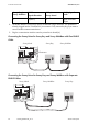


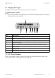


Table Of Contents
- 1 Information on this Manual
- 2 Sunny Island 4548-US/6048-US
- 3 Safety Precautions
- 4 Assembly
- 5 Opening and Closing
- 6 Electrical Connection
- 7 Control Elements
- 8 Initial Start-Up
- 9 Switching On and Off
- 10 Operation
- 11 Archiving Data on an SD Card
- 12 Additional Functions
- 12.1 Load Shedding
- 12.2 Sleep Mode
- 12.3 Time-Controlled Operation
- 12.4 Overload and Short-Circuit Behavior
- 12.5 Mixed Operation with Sunny Island inverters of Different Power
- 12.6 Device Faults and Autostart
- 12.7 Automatic Frequency Synchronization
- 12.8 Time-Controlled Standby
- 12.9 Behavior in the Event of a Failure in a Three-Phase System
- 13 Battery Management
- 14 Connecting External Sources
- 14.1 Generator
- 14.1.1 Parallel Connection
- 14.1.2 Generator Start Options
- 14.1.3 Generator Operation
- 14.1.4 Manual Generator Operation
- 14.1.5 Automatic Generator Operation
- 14.1.6 Limits and Power Control
- 14.1.7 Run Times
- 14.1.8 Operation Together with PV Inverters and Wind Power Inverters
- 14.1.9 Stopping the Generator
- 14.1.10 Stopping the Sunny Island
- 14.1.11 Disturbances
- 14.2 Grid
- 14.2.1 Limits of the Voltage Range and Frequency Range
- 14.2.2 Starting the Sunny Island
- 14.2.3 Operation in the Event of Grid Failure in a Grid-Tie Backup Configuration
- 14.2.4 Backup Operation and Anti-Islanding
- 14.2.5 Grid Reconnection
- 14.2.6 Grid Operation
- 14.2.7 Grid Failure
- 14.2.8 Disturbances
- 14.2.9 Limits and Power Control
- 14.2.10 Operation Together with PV Inverters and Wind Power Inverters
- 14.3 Generator and Grid
- 14.1 Generator
- 15 Relays
- 16 Multicluster Operation
- 16.1 Communication between the Sunny Island inverters
- 16.2 Initial Start-Up of the Multicluster System
- 16.3 Switching a Multicluster System On and Off
- 16.4 Generator Operation
- 16.5 Behavior with Different States of Charge
- 16.6 Testing the Multicluster Communication
- 16.7 Automatic Frequency Synchronization
- 16.8 Updating the Firmware
- 16.9 Error Handling in the Multicluster System
- 16.10 Grid Operation
- 16.11 Generator Emergency Operation
- 17 PV Inverters
- 18 Maintenance and Care
- 19 Parameter Lists
- 20 Troubleshooting
- 21 Accessories
- 22 Technical Data
- 23 Glossary
- 24 Contact

SMA America, LLC 6 Electrical Connection
Technical description SI4548_6048-US-TB_en-13 61
Connecting the Interface for External Communication
1. Remove the right-hand plug from the cable support sleeve.
2. Lead the cable from into the enclosure opening (C) from outside into the interior of the
Sunny Island.
3. Plug the cable into the "ComSmaIn" pin connector.
4. Fit the plug around the cable.
5. Plug the plug back into the designated opening in the cable support sleeve.
6. Lay the cable in the cable route (B).
7. Connect the conductors. Assignment pins in the RJ45 pin connector:
Item Description
A Slot for communication interface
B Cable route
C Enclosure opening in the base of the Sunny Island
Sunny Boy /
Sunny WebBox
RS485–
Signal allocation
RJ45 pin connector -
Sunny Island
RJ45 plug color
code
2 A (Data+) 3 white with green
stripes
5 GND 2 orange with white
stripes