
SI4548-US-10 Manual
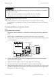

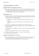

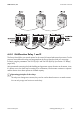


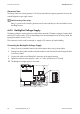

Table Of Contents
- 1 Information on this Manual
- 2 Sunny Island 4548-US/6048-US
- 3 Safety Precautions
- 4 Assembly
- 5 Opening and Closing
- 6 Electrical Connection
- 7 Control Elements
- 8 Initial Start-Up
- 9 Switching On and Off
- 10 Operation
- 11 Archiving Data on an SD Card
- 12 Additional Functions
- 12.1 Load Shedding
- 12.2 Sleep Mode
- 12.3 Time-Controlled Operation
- 12.4 Overload and Short-Circuit Behavior
- 12.5 Mixed Operation with Sunny Island inverters of Different Power
- 12.6 Device Faults and Autostart
- 12.7 Automatic Frequency Synchronization
- 12.8 Time-Controlled Standby
- 12.9 Behavior in the Event of a Failure in a Three-Phase System
- 13 Battery Management
- 14 Connecting External Sources
- 14.1 Generator
- 14.1.1 Parallel Connection
- 14.1.2 Generator Start Options
- 14.1.3 Generator Operation
- 14.1.4 Manual Generator Operation
- 14.1.5 Automatic Generator Operation
- 14.1.6 Limits and Power Control
- 14.1.7 Run Times
- 14.1.8 Operation Together with PV Inverters and Wind Power Inverters
- 14.1.9 Stopping the Generator
- 14.1.10 Stopping the Sunny Island
- 14.1.11 Disturbances
- 14.2 Grid
- 14.2.1 Limits of the Voltage Range and Frequency Range
- 14.2.2 Starting the Sunny Island
- 14.2.3 Operation in the Event of Grid Failure in a Grid-Tie Backup Configuration
- 14.2.4 Backup Operation and Anti-Islanding
- 14.2.5 Grid Reconnection
- 14.2.6 Grid Operation
- 14.2.7 Grid Failure
- 14.2.8 Disturbances
- 14.2.9 Limits and Power Control
- 14.2.10 Operation Together with PV Inverters and Wind Power Inverters
- 14.3 Generator and Grid
- 14.1 Generator
- 15 Relays
- 16 Multicluster Operation
- 16.1 Communication between the Sunny Island inverters
- 16.2 Initial Start-Up of the Multicluster System
- 16.3 Switching a Multicluster System On and Off
- 16.4 Generator Operation
- 16.5 Behavior with Different States of Charge
- 16.6 Testing the Multicluster Communication
- 16.7 Automatic Frequency Synchronization
- 16.8 Updating the Firmware
- 16.9 Error Handling in the Multicluster System
- 16.10 Grid Operation
- 16.11 Generator Emergency Operation
- 17 PV Inverters
- 18 Maintenance and Care
- 19 Parameter Lists
- 20 Troubleshooting
- 21 Accessories
- 22 Technical Data
- 23 Glossary
- 24 Contact

6 Electrical Connection SMA America, LLC
58 SI4548_6048-US-TB_en-13 Technical description
Generator Start
The Sunny Island can control generators. The Sunny Island directly supports generators that can be
started/stopped using a single contact.
6.4.5 BatVtgOut Voltage Supply
The battery voltage is conducted to the outside at these terminals. The battery voltage is fused at both
poles by PTC resistors (max. 0.75 A). Depending on the internal temperature of the Sunny Island, the
tripping threshold is at over 0.75 A.
This connection can be used, for example, to supply a DC contactor for load shedding.
Connecting the BatVtgOut Voltage Supply
1. Pierce a hole at a suitable location in the cable support sleeve using a sharp object.
2. Starting from the outside, lead the insulated conductors with bootlace ferrules through the hole
in the Sunny Island.
3. Connect the cables to the "BatVtgOut" connection of the 4-pole terminal.
4. Tighten the terminal screws (torque: 5 in-lbs. to 7 in-lbs. (0.56 Nm to 0.79 Nm)).
☑ The BatVtgOut voltage supply is connected.
Default setting of the relays
Relay 1 is preset to the "AutoGn" generator start function and relay 2 to the "AutoLodSoc" load
shedding function.