
SI4548-US-10 Manual
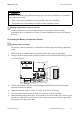

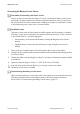

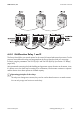


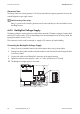

Table Of Contents
- 1 Information on this Manual
- 2 Sunny Island 4548-US/6048-US
- 3 Safety Precautions
- 4 Assembly
- 5 Opening and Closing
- 6 Electrical Connection
- 7 Control Elements
- 8 Initial Start-Up
- 9 Switching On and Off
- 10 Operation
- 11 Archiving Data on an SD Card
- 12 Additional Functions
- 12.1 Load Shedding
- 12.2 Sleep Mode
- 12.3 Time-Controlled Operation
- 12.4 Overload and Short-Circuit Behavior
- 12.5 Mixed Operation with Sunny Island inverters of Different Power
- 12.6 Device Faults and Autostart
- 12.7 Automatic Frequency Synchronization
- 12.8 Time-Controlled Standby
- 12.9 Behavior in the Event of a Failure in a Three-Phase System
- 13 Battery Management
- 14 Connecting External Sources
- 14.1 Generator
- 14.1.1 Parallel Connection
- 14.1.2 Generator Start Options
- 14.1.3 Generator Operation
- 14.1.4 Manual Generator Operation
- 14.1.5 Automatic Generator Operation
- 14.1.6 Limits and Power Control
- 14.1.7 Run Times
- 14.1.8 Operation Together with PV Inverters and Wind Power Inverters
- 14.1.9 Stopping the Generator
- 14.1.10 Stopping the Sunny Island
- 14.1.11 Disturbances
- 14.2 Grid
- 14.2.1 Limits of the Voltage Range and Frequency Range
- 14.2.2 Starting the Sunny Island
- 14.2.3 Operation in the Event of Grid Failure in a Grid-Tie Backup Configuration
- 14.2.4 Backup Operation and Anti-Islanding
- 14.2.5 Grid Reconnection
- 14.2.6 Grid Operation
- 14.2.7 Grid Failure
- 14.2.8 Disturbances
- 14.2.9 Limits and Power Control
- 14.2.10 Operation Together with PV Inverters and Wind Power Inverters
- 14.3 Generator and Grid
- 14.1 Generator
- 15 Relays
- 16 Multicluster Operation
- 16.1 Communication between the Sunny Island inverters
- 16.2 Initial Start-Up of the Multicluster System
- 16.3 Switching a Multicluster System On and Off
- 16.4 Generator Operation
- 16.5 Behavior with Different States of Charge
- 16.6 Testing the Multicluster Communication
- 16.7 Automatic Frequency Synchronization
- 16.8 Updating the Firmware
- 16.9 Error Handling in the Multicluster System
- 16.10 Grid Operation
- 16.11 Generator Emergency Operation
- 17 PV Inverters
- 18 Maintenance and Care
- 19 Parameter Lists
- 20 Troubleshooting
- 21 Accessories
- 22 Technical Data
- 23 Glossary
- 24 Contact

6 Electrical Connection SMA America, LLC
56 SI4548_6048-US-TB_en-13 Technical description
Connection to the Relay Contact
1. Pierce a hole at a suitable location in the cable support sleeve using a sharp object.
2. Starting from the outside, lead the insulated conductors with bootlace ferrules through the hole
in the Sunny Island.
3. Cut an appropriate piece from the silicone tube (included in scope of delivery) and pull it over
the insulated conductors.
4. Connect the conductors to the supplied three-pole terminals. The pins have the following
meaning:
– NC: normally closed (when the Sunny Island is
off, the relay is closed)
– C: Contact (front contact)
– NO: normally opened (when the Sunny Island is
off, the relay is open)
5. Tighten the terminals (torque: 5 in-lbs. to 7 in-lbs. (0.56 Nm to 0.79 Nm)).
6. Insert the three-pole terminal into the corresponding pin connector on the Sunny Island.
Danger to life from electric shock due to incorrect insulation.
• Securely disconnect the relay cable from the communication area and the AC area.
• Strip the insulated conductors of the relay cable.
• Sheathe all relay cables installed using the silicone tube provided.
• Do not operate the device without the silicone tube.