
SI4548-US-10 Manual
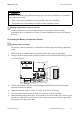


Table Of Contents
- 1 Information on this Manual
- 2 Sunny Island 4548-US/6048-US
- 3 Safety Precautions
- 4 Assembly
- 5 Opening and Closing
- 6 Electrical Connection
- 7 Control Elements
- 8 Initial Start-Up
- 9 Switching On and Off
- 10 Operation
- 11 Archiving Data on an SD Card
- 12 Additional Functions
- 12.1 Load Shedding
- 12.2 Sleep Mode
- 12.3 Time-Controlled Operation
- 12.4 Overload and Short-Circuit Behavior
- 12.5 Mixed Operation with Sunny Island inverters of Different Power
- 12.6 Device Faults and Autostart
- 12.7 Automatic Frequency Synchronization
- 12.8 Time-Controlled Standby
- 12.9 Behavior in the Event of a Failure in a Three-Phase System
- 13 Battery Management
- 14 Connecting External Sources
- 14.1 Generator
- 14.1.1 Parallel Connection
- 14.1.2 Generator Start Options
- 14.1.3 Generator Operation
- 14.1.4 Manual Generator Operation
- 14.1.5 Automatic Generator Operation
- 14.1.6 Limits and Power Control
- 14.1.7 Run Times
- 14.1.8 Operation Together with PV Inverters and Wind Power Inverters
- 14.1.9 Stopping the Generator
- 14.1.10 Stopping the Sunny Island
- 14.1.11 Disturbances
- 14.2 Grid
- 14.2.1 Limits of the Voltage Range and Frequency Range
- 14.2.2 Starting the Sunny Island
- 14.2.3 Operation in the Event of Grid Failure in a Grid-Tie Backup Configuration
- 14.2.4 Backup Operation and Anti-Islanding
- 14.2.5 Grid Reconnection
- 14.2.6 Grid Operation
- 14.2.7 Grid Failure
- 14.2.8 Disturbances
- 14.2.9 Limits and Power Control
- 14.2.10 Operation Together with PV Inverters and Wind Power Inverters
- 14.3 Generator and Grid
- 14.1 Generator
- 15 Relays
- 16 Multicluster Operation
- 16.1 Communication between the Sunny Island inverters
- 16.2 Initial Start-Up of the Multicluster System
- 16.3 Switching a Multicluster System On and Off
- 16.4 Generator Operation
- 16.5 Behavior with Different States of Charge
- 16.6 Testing the Multicluster Communication
- 16.7 Automatic Frequency Synchronization
- 16.8 Updating the Firmware
- 16.9 Error Handling in the Multicluster System
- 16.10 Grid Operation
- 16.11 Generator Emergency Operation
- 17 PV Inverters
- 18 Maintenance and Care
- 19 Parameter Lists
- 20 Troubleshooting
- 21 Accessories
- 22 Technical Data
- 23 Glossary
- 24 Contact

SMA America, LLC 6 Electrical Connection
Technical description SI4548_6048-US-TB_en-13 51
Connecting the Battery Temperature Sensor
1. Pierce a hole at a suitable location in the cable support sleeve using a sharp object.
2. Starting from the outside, lead the insulated conductors with bootlace ferrules through the hole
in the Sunny Island.
3. Connect the insulated conductors correspondingly to the "BatTmp" terminal of the 4-pole
terminal included in the delivery.
4. Tighten the terminals (torque: 5 in-lbs. to 7 in-lbs. (0.56 Nm to 0.79 Nm)).
5. Insert the 4-pole terminal into the "BatTmp" pin connector on the Sunny Island.
6. Attach the battery temperature sensor to the outside of one of the battery cells. Choose a spot
between two cells and in the central area of the battery storage system. The heat generation
during operation is the greatest there.
Destruction of the battery through deep discharge as a result of the installation of an unsuitable
battery temperature sensor.
• Only use the battery temperature sensor included in the scope of delivery.
• Do not drill holes into the battery to install the battery temperature sensor.
Battery temperature sensor in a cluster
A battery temperature sensor is provided with each Sunny Island. Only one battery
temperature sensor is required for a cluster. Connect the temperature sensor to the master of
the cluster.
Polarity of the conductors
The polarity of the two conductors is irrelevant for the functioning of the battery temperature
sensor.