
SI4548-US-10 Manual
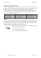

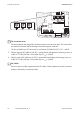


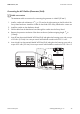

Table Of Contents
- 1 Information on this Manual
- 2 Sunny Island 4548-US/6048-US
- 3 Safety Precautions
- 4 Assembly
- 5 Opening and Closing
- 6 Electrical Connection
- 7 Control Elements
- 8 Initial Start-Up
- 9 Switching On and Off
- 10 Operation
- 11 Archiving Data on an SD Card
- 12 Additional Functions
- 12.1 Load Shedding
- 12.2 Sleep Mode
- 12.3 Time-Controlled Operation
- 12.4 Overload and Short-Circuit Behavior
- 12.5 Mixed Operation with Sunny Island inverters of Different Power
- 12.6 Device Faults and Autostart
- 12.7 Automatic Frequency Synchronization
- 12.8 Time-Controlled Standby
- 12.9 Behavior in the Event of a Failure in a Three-Phase System
- 13 Battery Management
- 14 Connecting External Sources
- 14.1 Generator
- 14.1.1 Parallel Connection
- 14.1.2 Generator Start Options
- 14.1.3 Generator Operation
- 14.1.4 Manual Generator Operation
- 14.1.5 Automatic Generator Operation
- 14.1.6 Limits and Power Control
- 14.1.7 Run Times
- 14.1.8 Operation Together with PV Inverters and Wind Power Inverters
- 14.1.9 Stopping the Generator
- 14.1.10 Stopping the Sunny Island
- 14.1.11 Disturbances
- 14.2 Grid
- 14.2.1 Limits of the Voltage Range and Frequency Range
- 14.2.2 Starting the Sunny Island
- 14.2.3 Operation in the Event of Grid Failure in a Grid-Tie Backup Configuration
- 14.2.4 Backup Operation and Anti-Islanding
- 14.2.5 Grid Reconnection
- 14.2.6 Grid Operation
- 14.2.7 Grid Failure
- 14.2.8 Disturbances
- 14.2.9 Limits and Power Control
- 14.2.10 Operation Together with PV Inverters and Wind Power Inverters
- 14.3 Generator and Grid
- 14.1 Generator
- 15 Relays
- 16 Multicluster Operation
- 16.1 Communication between the Sunny Island inverters
- 16.2 Initial Start-Up of the Multicluster System
- 16.3 Switching a Multicluster System On and Off
- 16.4 Generator Operation
- 16.5 Behavior with Different States of Charge
- 16.6 Testing the Multicluster Communication
- 16.7 Automatic Frequency Synchronization
- 16.8 Updating the Firmware
- 16.9 Error Handling in the Multicluster System
- 16.10 Grid Operation
- 16.11 Generator Emergency Operation
- 17 PV Inverters
- 18 Maintenance and Care
- 19 Parameter Lists
- 20 Troubleshooting
- 21 Accessories
- 22 Technical Data
- 23 Glossary
- 24 Contact

SMA America, LLC 6 Electrical Connection
Technical description SI4548_6048-US-TB_en-13 47
Connecting the AC1 Cables:
1. Install a conduit with a diameter of
3
/
4
in. (19 mm) at the left opening on the left side of the
Sunny Island enclosure. Attach the conduit on the inside of the Sunny Island with a counter nut.
2. Install the conduit on the distribution board.
3. Pull the cable from the distribution board through the conduit into the Sunny Island.
4. Remove the protective insulation of the three conductors (isolation stripping length:
3
⁄
4
in.
(18 mm)).
5. Insert PE into the terminal labeled "AC1 Loads/Sunny Boys" and tighten the fastening screw with
a torque of 22 in-lbs. (2.5 Nm). Use a torque wrench with flat-blade screwdriver bit SZS 1.0 x 6.5.
6. Insert N and L into the terminals labeled "AC1 Loads/Sunny Boys" and tighten the fastening
screws with a torque of 22 in-lbs. (2.5 Nm). Use a torque wrench with flat-blade screwdriver bit
SZS 1.0 x 6.5.
☑ The AC1 cables are connected.
Cable cross-section
The maximum cable cross-section for connecting the loads/PV inverters is 4 AWG (25 mm²).