
SI4548-US-10 Manual
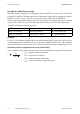

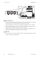


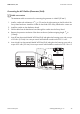

Table Of Contents
- 1 Information on this Manual
- 2 Sunny Island 4548-US/6048-US
- 3 Safety Precautions
- 4 Assembly
- 5 Opening and Closing
- 6 Electrical Connection
- 7 Control Elements
- 8 Initial Start-Up
- 9 Switching On and Off
- 10 Operation
- 11 Archiving Data on an SD Card
- 12 Additional Functions
- 12.1 Load Shedding
- 12.2 Sleep Mode
- 12.3 Time-Controlled Operation
- 12.4 Overload and Short-Circuit Behavior
- 12.5 Mixed Operation with Sunny Island inverters of Different Power
- 12.6 Device Faults and Autostart
- 12.7 Automatic Frequency Synchronization
- 12.8 Time-Controlled Standby
- 12.9 Behavior in the Event of a Failure in a Three-Phase System
- 13 Battery Management
- 14 Connecting External Sources
- 14.1 Generator
- 14.1.1 Parallel Connection
- 14.1.2 Generator Start Options
- 14.1.3 Generator Operation
- 14.1.4 Manual Generator Operation
- 14.1.5 Automatic Generator Operation
- 14.1.6 Limits and Power Control
- 14.1.7 Run Times
- 14.1.8 Operation Together with PV Inverters and Wind Power Inverters
- 14.1.9 Stopping the Generator
- 14.1.10 Stopping the Sunny Island
- 14.1.11 Disturbances
- 14.2 Grid
- 14.2.1 Limits of the Voltage Range and Frequency Range
- 14.2.2 Starting the Sunny Island
- 14.2.3 Operation in the Event of Grid Failure in a Grid-Tie Backup Configuration
- 14.2.4 Backup Operation and Anti-Islanding
- 14.2.5 Grid Reconnection
- 14.2.6 Grid Operation
- 14.2.7 Grid Failure
- 14.2.8 Disturbances
- 14.2.9 Limits and Power Control
- 14.2.10 Operation Together with PV Inverters and Wind Power Inverters
- 14.3 Generator and Grid
- 14.1 Generator
- 15 Relays
- 16 Multicluster Operation
- 16.1 Communication between the Sunny Island inverters
- 16.2 Initial Start-Up of the Multicluster System
- 16.3 Switching a Multicluster System On and Off
- 16.4 Generator Operation
- 16.5 Behavior with Different States of Charge
- 16.6 Testing the Multicluster Communication
- 16.7 Automatic Frequency Synchronization
- 16.8 Updating the Firmware
- 16.9 Error Handling in the Multicluster System
- 16.10 Grid Operation
- 16.11 Generator Emergency Operation
- 17 PV Inverters
- 18 Maintenance and Care
- 19 Parameter Lists
- 20 Troubleshooting
- 21 Accessories
- 22 Technical Data
- 23 Glossary
- 24 Contact

6 Electrical Connection SMA America, LLC
46 SI4548_6048-US-TB_en-13 Technical description
6.3.2 AC1 (Loads/Sunny Boys)
The sub-distribution of the stand-alone grid (e.g. loads, PV inverter, wind power inverter) is to be
connected to output AC1 of the Sunny Island.
If you want to fuse individual load circuits in a 120 V grid separately, install circuit breakers with a
rated current of up to 20 A: the Sunny Island can safely trigger circuit breakers of up to 20 A.
If you install circuit breakers with a higher rated current, the Sunny Island may not trigger these. In this
case the DC breaker in the Sunny Island would trigger and the Sunny Island would disconnect itself
(see Section 9.5 "Reactivating the Device Following Automatic Shutdown", page 75).
Cable lengths in single-phase, parallel, split-phase, double split-phase and
three-phase systems
The AC lines between the Sunny Island and the sub-distribution of a system must have the same
cable cross-section and the same length for all parallel connected devices.
Distributing loads and AC feed-in generators in multiple-phase systems
Distribute the feed-in power and the consumed power of the loads and AC feed-in generators
as equally as possible across all line conductors of the plant.
Connection in a split-phase system
In a split-phase system, connect the master to line conductor L1 and the slave 1 to line
conductor L2 (see Section 2.2 "At a Glance", page 22).
Double split-phase system
In a double split-phase system, connect the master and slave 2 to line conductor L1.
In a double split-phase system, connect slave 1 and slave 3 to line conductor L2.
Connection in a three-phase system
Always install the master on line conductor L1, slave 1 on L2 and slave 2 on L3. This installation
has a right-hand rotating magnetic field.
Failure of a line conductor within a three-phase system
If in a three-phase system a line conductor fails on the master, the cluster stops. If a line
conductor fails on a slave, the cluster can either continue to operate or switch off. Whether the
cluster continues to work or switches off depends on the setting of the parameter
"250.30 RnMod" (see Section 19.2.5 "System Settings (250#)", page 190).