
SI4548-US-10 Manual
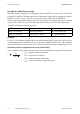


Table Of Contents
- 1 Information on this Manual
- 2 Sunny Island 4548-US/6048-US
- 3 Safety Precautions
- 4 Assembly
- 5 Opening and Closing
- 6 Electrical Connection
- 7 Control Elements
- 8 Initial Start-Up
- 9 Switching On and Off
- 10 Operation
- 11 Archiving Data on an SD Card
- 12 Additional Functions
- 12.1 Load Shedding
- 12.2 Sleep Mode
- 12.3 Time-Controlled Operation
- 12.4 Overload and Short-Circuit Behavior
- 12.5 Mixed Operation with Sunny Island inverters of Different Power
- 12.6 Device Faults and Autostart
- 12.7 Automatic Frequency Synchronization
- 12.8 Time-Controlled Standby
- 12.9 Behavior in the Event of a Failure in a Three-Phase System
- 13 Battery Management
- 14 Connecting External Sources
- 14.1 Generator
- 14.1.1 Parallel Connection
- 14.1.2 Generator Start Options
- 14.1.3 Generator Operation
- 14.1.4 Manual Generator Operation
- 14.1.5 Automatic Generator Operation
- 14.1.6 Limits and Power Control
- 14.1.7 Run Times
- 14.1.8 Operation Together with PV Inverters and Wind Power Inverters
- 14.1.9 Stopping the Generator
- 14.1.10 Stopping the Sunny Island
- 14.1.11 Disturbances
- 14.2 Grid
- 14.2.1 Limits of the Voltage Range and Frequency Range
- 14.2.2 Starting the Sunny Island
- 14.2.3 Operation in the Event of Grid Failure in a Grid-Tie Backup Configuration
- 14.2.4 Backup Operation and Anti-Islanding
- 14.2.5 Grid Reconnection
- 14.2.6 Grid Operation
- 14.2.7 Grid Failure
- 14.2.8 Disturbances
- 14.2.9 Limits and Power Control
- 14.2.10 Operation Together with PV Inverters and Wind Power Inverters
- 14.3 Generator and Grid
- 14.1 Generator
- 15 Relays
- 16 Multicluster Operation
- 16.1 Communication between the Sunny Island inverters
- 16.2 Initial Start-Up of the Multicluster System
- 16.3 Switching a Multicluster System On and Off
- 16.4 Generator Operation
- 16.5 Behavior with Different States of Charge
- 16.6 Testing the Multicluster Communication
- 16.7 Automatic Frequency Synchronization
- 16.8 Updating the Firmware
- 16.9 Error Handling in the Multicluster System
- 16.10 Grid Operation
- 16.11 Generator Emergency Operation
- 17 PV Inverters
- 18 Maintenance and Care
- 19 Parameter Lists
- 20 Troubleshooting
- 21 Accessories
- 22 Technical Data
- 23 Glossary
- 24 Contact

6 Electrical Connection SMA America, LLC
42 SI4548_6048-US-TB_en-13 Technical description
Example for Cable Dimensioning
With a 48 V battery voltage and an outgoing AC power of 4,500 W, a current of up to 100 A flows
through the SI 4548-US-10 battery cable. At the same battery voltage and an outgoing AC power of
6,000 W, a current of up to 130 A flows through the battery cable of the SI 6048-US-10.
The current flowing through the battery line causes a power loss and a voltage drop with every meter
of plain battery cable. You can use the following table to find the power loss and voltage drop
associated with different cable cross-sections.
Example:
For a 33 ft. (10 m) distance between the Sunny Island and the battery, at least 66 ft. (20 m) of line
is needed (distance there and back). Using a cross-section of AWG 2/0 (70 mm²), 100 A (nominal
current of the battery) causes a power loss of 120 W in total and an effective voltage drop of 0.9 V.
Calculation of the averaged nominal current of the battery
You can calculate the averaged nominal current of the connected battery using the following formula:
I
Bat
= Nominal current of the battery
P
AC
= AC power of the inverter
U
Bat
= Nominal voltage of the battery
η
INV
= Inverter efficiency at a given AC power
Cable cross-section Power loss Voltage drop
AWG 2/0 (70 mm²) 1.8 W/ft. (6 W/m) 14 mV/ft. (45 mV/m)
AWG 3/0 (95 mm²) 1.4 W/ft. (4.7 W/m) 11 mV/ft (35 mV/m)