
SI4548-US-10 Manual
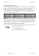

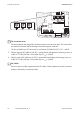


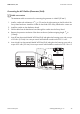

Table Of Contents
- 1 Information on this Manual
- 2 Sunny Island 4548-US/6048-US
- 3 Safety Precautions
- 4 Assembly
- 5 Opening and Closing
- 6 Electrical Connection
- 7 Control Elements
- 8 Initial Start-Up
- 9 Switching On and Off
- 10 Operation
- 11 Archiving Data on an SD Card
- 12 Additional Functions
- 12.1 Load Shedding
- 12.2 Sleep Mode
- 12.3 Time-Controlled Operation
- 12.4 Overload and Short-Circuit Behavior
- 12.5 Mixed Operation with Sunny Island inverters of Different Power
- 12.6 Device Faults and Autostart
- 12.7 Automatic Frequency Synchronization
- 12.8 Time-Controlled Standby
- 12.9 Behavior in the Event of a Failure in a Three-Phase System
- 13 Battery Management
- 14 Connecting External Sources
- 14.1 Generator
- 14.1.1 Parallel Connection
- 14.1.2 Generator Start Options
- 14.1.3 Generator Operation
- 14.1.4 Manual Generator Operation
- 14.1.5 Automatic Generator Operation
- 14.1.6 Limits and Power Control
- 14.1.7 Run Times
- 14.1.8 Operation Together with PV Inverters and Wind Power Inverters
- 14.1.9 Stopping the Generator
- 14.1.10 Stopping the Sunny Island
- 14.1.11 Disturbances
- 14.2 Grid
- 14.2.1 Limits of the Voltage Range and Frequency Range
- 14.2.2 Starting the Sunny Island
- 14.2.3 Operation in the Event of Grid Failure in a Grid-Tie Backup Configuration
- 14.2.4 Backup Operation and Anti-Islanding
- 14.2.5 Grid Reconnection
- 14.2.6 Grid Operation
- 14.2.7 Grid Failure
- 14.2.8 Disturbances
- 14.2.9 Limits and Power Control
- 14.2.10 Operation Together with PV Inverters and Wind Power Inverters
- 14.3 Generator and Grid
- 14.1 Generator
- 15 Relays
- 16 Multicluster Operation
- 16.1 Communication between the Sunny Island inverters
- 16.2 Initial Start-Up of the Multicluster System
- 16.3 Switching a Multicluster System On and Off
- 16.4 Generator Operation
- 16.5 Behavior with Different States of Charge
- 16.6 Testing the Multicluster Communication
- 16.7 Automatic Frequency Synchronization
- 16.8 Updating the Firmware
- 16.9 Error Handling in the Multicluster System
- 16.10 Grid Operation
- 16.11 Generator Emergency Operation
- 17 PV Inverters
- 18 Maintenance and Care
- 19 Parameter Lists
- 20 Troubleshooting
- 21 Accessories
- 22 Technical Data
- 23 Glossary
- 24 Contact

SMA America, LLC 6 Electrical Connection
Technical description SI4548_6048-US-TB_en-13 41
6.2 DC Connection
6.2.1 Safety Precautions/Conditions
Connect a suitable battery to the DC side (see Section 22 "Technical Data", page 225).
The DC connection must be made in accordance with all locally applicable directives and regulations.
6.2.2 Cable Dimensioning
Function impairments of devices on the DC busbar.
The Sunny Island is not suitable for use with DC supply grids. Function impairment can occur on
devices installed on the DC side of a Sunny Island with cables exceeding 98 ft. (30 m) and with a
flexible connection.
• Only use fixed installations.
• Do not use cables of lengths greater than 98 ft. (30 m) between the Sunny Island and the
battery and/or DC device.
Danger to life due to chemical burns in the event of leaking acid
Acid can escape in the event of improper handling of the battery.
• Observe all safety indications and warnings provided by the battery manufacturer.
• Use special (insulated) tools to mount and install the battery.
• Provide sufficient air supply in the room in which the battery is. When gases are produced by
the battery, these cannot be allowed to collect.
Keep the lines to the battery as short as possible.
The battery cables should be as short as possible. Long cables and insufficient cable diameters
reduce the system efficiency as well as the overload capacity. Do not lay the battery lead under
plaster or in armored plastic pipes.
Selection of the cable cross-section
SMA recommends choosing cable cross-sections greater than those given by
National Electrical Code
®
310.15 when the cable lengths exceed 33 ft. (10 m).