
SI4548-US-10 Manual
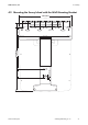


Table Of Contents
- 1 Information on this Manual
- 2 Sunny Island 4548-US/6048-US
- 3 Safety Precautions
- 4 Assembly
- 5 Opening and Closing
- 6 Electrical Connection
- 7 Control Elements
- 8 Initial Start-Up
- 9 Switching On and Off
- 10 Operation
- 11 Archiving Data on an SD Card
- 12 Additional Functions
- 12.1 Load Shedding
- 12.2 Sleep Mode
- 12.3 Time-Controlled Operation
- 12.4 Overload and Short-Circuit Behavior
- 12.5 Mixed Operation with Sunny Island inverters of Different Power
- 12.6 Device Faults and Autostart
- 12.7 Automatic Frequency Synchronization
- 12.8 Time-Controlled Standby
- 12.9 Behavior in the Event of a Failure in a Three-Phase System
- 13 Battery Management
- 14 Connecting External Sources
- 14.1 Generator
- 14.1.1 Parallel Connection
- 14.1.2 Generator Start Options
- 14.1.3 Generator Operation
- 14.1.4 Manual Generator Operation
- 14.1.5 Automatic Generator Operation
- 14.1.6 Limits and Power Control
- 14.1.7 Run Times
- 14.1.8 Operation Together with PV Inverters and Wind Power Inverters
- 14.1.9 Stopping the Generator
- 14.1.10 Stopping the Sunny Island
- 14.1.11 Disturbances
- 14.2 Grid
- 14.2.1 Limits of the Voltage Range and Frequency Range
- 14.2.2 Starting the Sunny Island
- 14.2.3 Operation in the Event of Grid Failure in a Grid-Tie Backup Configuration
- 14.2.4 Backup Operation and Anti-Islanding
- 14.2.5 Grid Reconnection
- 14.2.6 Grid Operation
- 14.2.7 Grid Failure
- 14.2.8 Disturbances
- 14.2.9 Limits and Power Control
- 14.2.10 Operation Together with PV Inverters and Wind Power Inverters
- 14.3 Generator and Grid
- 14.1 Generator
- 15 Relays
- 16 Multicluster Operation
- 16.1 Communication between the Sunny Island inverters
- 16.2 Initial Start-Up of the Multicluster System
- 16.3 Switching a Multicluster System On and Off
- 16.4 Generator Operation
- 16.5 Behavior with Different States of Charge
- 16.6 Testing the Multicluster Communication
- 16.7 Automatic Frequency Synchronization
- 16.8 Updating the Firmware
- 16.9 Error Handling in the Multicluster System
- 16.10 Grid Operation
- 16.11 Generator Emergency Operation
- 17 PV Inverters
- 18 Maintenance and Care
- 19 Parameter Lists
- 20 Troubleshooting
- 21 Accessories
- 22 Technical Data
- 23 Glossary
- 24 Contact

6 Electrical Connection SMA America, LLC
40 SI4548_6048-US-TB_en-13 Technical description
Connecting the grounding conductor
1. Install a conduit with a diameter of 1
1
/
2
in. (38.1 mm) at the opening in the center of the
Sunny Island. Attach the conduit in the inside of the Sunny Island using the appropriate nut.
2. Pull the cabling through the supply line from the inside of the distribution board into the
enclosure of the Sunny Island.
3. Strip the insulation of the grounding conductor.
4. Plug the grounding conductor into the DC terminal block for grounding and tighten the fastening
screw to a torque of 21 ft-lbs. (28 Nm). Use an Allen key of
5
⁄
16
in. (8 mm).
☑ The grounding conductor is connected.
Calculating the Cross-Section of a Grounding Conductor
SMA cannot state generally valid values for the cross-section of the grounding conductor required for
the external grounding of the battery. The cable dimensions depend on the type and size of the
battery connected, the external fuse (DC side) and the material used in the grounding conductor.
Calculating the required grounding conductor cross-section according to applicable
standards
Exact calculation of the grounding conductor cross-section must take account of the regionally
applicable standards and directives (e.g. National Electric Code
®
Article 250.122).