
SI4548-US-10 Manual
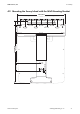


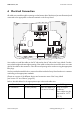
Table Of Contents
- 1 Information on this Manual
- 2 Sunny Island 4548-US/6048-US
- 3 Safety Precautions
- 4 Assembly
- 5 Opening and Closing
- 6 Electrical Connection
- 7 Control Elements
- 8 Initial Start-Up
- 9 Switching On and Off
- 10 Operation
- 11 Archiving Data on an SD Card
- 12 Additional Functions
- 12.1 Load Shedding
- 12.2 Sleep Mode
- 12.3 Time-Controlled Operation
- 12.4 Overload and Short-Circuit Behavior
- 12.5 Mixed Operation with Sunny Island inverters of Different Power
- 12.6 Device Faults and Autostart
- 12.7 Automatic Frequency Synchronization
- 12.8 Time-Controlled Standby
- 12.9 Behavior in the Event of a Failure in a Three-Phase System
- 13 Battery Management
- 14 Connecting External Sources
- 14.1 Generator
- 14.1.1 Parallel Connection
- 14.1.2 Generator Start Options
- 14.1.3 Generator Operation
- 14.1.4 Manual Generator Operation
- 14.1.5 Automatic Generator Operation
- 14.1.6 Limits and Power Control
- 14.1.7 Run Times
- 14.1.8 Operation Together with PV Inverters and Wind Power Inverters
- 14.1.9 Stopping the Generator
- 14.1.10 Stopping the Sunny Island
- 14.1.11 Disturbances
- 14.2 Grid
- 14.2.1 Limits of the Voltage Range and Frequency Range
- 14.2.2 Starting the Sunny Island
- 14.2.3 Operation in the Event of Grid Failure in a Grid-Tie Backup Configuration
- 14.2.4 Backup Operation and Anti-Islanding
- 14.2.5 Grid Reconnection
- 14.2.6 Grid Operation
- 14.2.7 Grid Failure
- 14.2.8 Disturbances
- 14.2.9 Limits and Power Control
- 14.2.10 Operation Together with PV Inverters and Wind Power Inverters
- 14.3 Generator and Grid
- 14.1 Generator
- 15 Relays
- 16 Multicluster Operation
- 16.1 Communication between the Sunny Island inverters
- 16.2 Initial Start-Up of the Multicluster System
- 16.3 Switching a Multicluster System On and Off
- 16.4 Generator Operation
- 16.5 Behavior with Different States of Charge
- 16.6 Testing the Multicluster Communication
- 16.7 Automatic Frequency Synchronization
- 16.8 Updating the Firmware
- 16.9 Error Handling in the Multicluster System
- 16.10 Grid Operation
- 16.11 Generator Emergency Operation
- 17 PV Inverters
- 18 Maintenance and Care
- 19 Parameter Lists
- 20 Troubleshooting
- 21 Accessories
- 22 Technical Data
- 23 Glossary
- 24 Contact

SMA America, LLC 6 Electrical Connection
Technical description SI4548_6048-US-TB_en-13 39
6.1 Grounding
Danger to life due to electric shock
• Fuse the sub-distribution of the generator or the utility grid at input AC2 of the Sunny Island
with an overcurrent protective device (Branch Circuit Protection).
• Ensure that the overcurrent protective device complies with the specifications of the
National Electrical Code
®
, ANSI/NFPA 70.
• Use an overcurrent protective device for a maximum 70 A.
Danger to life from electric shock due to faulty grounding.
To allow different types of grounding, the N connection of the Sunny Island is NOT connected to
PE at the factory. However, since a connection between N and PE is required for correct operation,
this must be done outside of the Sunny Island.
• Before commissioning, connect the Sunny Island 4548-US/6048-US and all other devices of
the stand-alone grid to a grounded grid.
• Take the National Electrical Code
®
, ANSI/NFPA 70, and all locally applicable standards
and directives into consideration.
External grounding of the negative pole of the battery
External grounding of the negative pole of the batteries is possible because the batteries and
the grid side are galvanically insulated within the Sunny Island.
• Dimension the cross-section of the grounding conductor sufficiently. Thus, you are
ensuring that in the event of a fault the high currents occurring can be discharged with an
external grounding.
• If grounding of the negative pole of the battery is necessary, assemble this outside of the
Sunny Island.