
SI4548-US-10 Manual
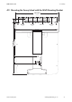


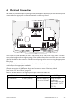
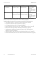
Table Of Contents
- 1 Information on this Manual
- 2 Sunny Island 4548-US/6048-US
- 3 Safety Precautions
- 4 Assembly
- 5 Opening and Closing
- 6 Electrical Connection
- 7 Control Elements
- 8 Initial Start-Up
- 9 Switching On and Off
- 10 Operation
- 11 Archiving Data on an SD Card
- 12 Additional Functions
- 12.1 Load Shedding
- 12.2 Sleep Mode
- 12.3 Time-Controlled Operation
- 12.4 Overload and Short-Circuit Behavior
- 12.5 Mixed Operation with Sunny Island inverters of Different Power
- 12.6 Device Faults and Autostart
- 12.7 Automatic Frequency Synchronization
- 12.8 Time-Controlled Standby
- 12.9 Behavior in the Event of a Failure in a Three-Phase System
- 13 Battery Management
- 14 Connecting External Sources
- 14.1 Generator
- 14.1.1 Parallel Connection
- 14.1.2 Generator Start Options
- 14.1.3 Generator Operation
- 14.1.4 Manual Generator Operation
- 14.1.5 Automatic Generator Operation
- 14.1.6 Limits and Power Control
- 14.1.7 Run Times
- 14.1.8 Operation Together with PV Inverters and Wind Power Inverters
- 14.1.9 Stopping the Generator
- 14.1.10 Stopping the Sunny Island
- 14.1.11 Disturbances
- 14.2 Grid
- 14.2.1 Limits of the Voltage Range and Frequency Range
- 14.2.2 Starting the Sunny Island
- 14.2.3 Operation in the Event of Grid Failure in a Grid-Tie Backup Configuration
- 14.2.4 Backup Operation and Anti-Islanding
- 14.2.5 Grid Reconnection
- 14.2.6 Grid Operation
- 14.2.7 Grid Failure
- 14.2.8 Disturbances
- 14.2.9 Limits and Power Control
- 14.2.10 Operation Together with PV Inverters and Wind Power Inverters
- 14.3 Generator and Grid
- 14.1 Generator
- 15 Relays
- 16 Multicluster Operation
- 16.1 Communication between the Sunny Island inverters
- 16.2 Initial Start-Up of the Multicluster System
- 16.3 Switching a Multicluster System On and Off
- 16.4 Generator Operation
- 16.5 Behavior with Different States of Charge
- 16.6 Testing the Multicluster Communication
- 16.7 Automatic Frequency Synchronization
- 16.8 Updating the Firmware
- 16.9 Error Handling in the Multicluster System
- 16.10 Grid Operation
- 16.11 Generator Emergency Operation
- 17 PV Inverters
- 18 Maintenance and Care
- 19 Parameter Lists
- 20 Troubleshooting
- 21 Accessories
- 22 Technical Data
- 23 Glossary
- 24 Contact

6 Electrical Connection SMA America, LLC
38 SI4548_6048-US-TB_en-13 Technical description
An overview of the different devices and their connection areas of the Sunny Island 4548-US/
6048-US can be found in section (see Section 2.2 "At a Glance", page 22).
Detailed installation descriptions of the connections are provided in the following sections:
• Grounding (see Section 6.5 "Interface for External Communication", page 60)
• DC Connection (see Section 6.2 "DC Connection", page 41)
• AC Connection (see Section 6.3 "AC Connection", page 45)
• Battery Temperature Sensor (see Section 6.4.1 "Battery Temperature Sensor", page 50)
• Battery Current Sensor (see Section 6.4.2 "Battery Current Sensor", page 52)
• Communication for Multi-Device Connection (see Section 6.4.3 "Communication for
Multi-Device Connection", page 54)
• Multifunction Relay 1 and 2 (see Section 6.4.4 "Multifunction Relay 1 and 2", page 55)
• External Communication (see Section 6.5 "Interface for External Communication", page 60)
AC connections 22 in-lbs. (2.5 Nm) AWG 4 (25 mm²) Only use copper
conductors.
These cables must be
approved for 167°F
(75°C).
Additional connections 5 in-lbs. to 7 in-lbs.
(0.56 Nm
to
0.79 Nm)
AWG 30 to AWG 12
(0.05 mm² to 4 mm²)
Only use copper
conductors.
These cables must be
approved for 167°F
(75°C).
Terminal Torque Cable size Cable type