
SI4548-US-10 Manual
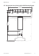


Table Of Contents
- 1 Information on this Manual
- 2 Sunny Island 4548-US/6048-US
- 3 Safety Precautions
- 4 Assembly
- 5 Opening and Closing
- 6 Electrical Connection
- 7 Control Elements
- 8 Initial Start-Up
- 9 Switching On and Off
- 10 Operation
- 11 Archiving Data on an SD Card
- 12 Additional Functions
- 12.1 Load Shedding
- 12.2 Sleep Mode
- 12.3 Time-Controlled Operation
- 12.4 Overload and Short-Circuit Behavior
- 12.5 Mixed Operation with Sunny Island inverters of Different Power
- 12.6 Device Faults and Autostart
- 12.7 Automatic Frequency Synchronization
- 12.8 Time-Controlled Standby
- 12.9 Behavior in the Event of a Failure in a Three-Phase System
- 13 Battery Management
- 14 Connecting External Sources
- 14.1 Generator
- 14.1.1 Parallel Connection
- 14.1.2 Generator Start Options
- 14.1.3 Generator Operation
- 14.1.4 Manual Generator Operation
- 14.1.5 Automatic Generator Operation
- 14.1.6 Limits and Power Control
- 14.1.7 Run Times
- 14.1.8 Operation Together with PV Inverters and Wind Power Inverters
- 14.1.9 Stopping the Generator
- 14.1.10 Stopping the Sunny Island
- 14.1.11 Disturbances
- 14.2 Grid
- 14.2.1 Limits of the Voltage Range and Frequency Range
- 14.2.2 Starting the Sunny Island
- 14.2.3 Operation in the Event of Grid Failure in a Grid-Tie Backup Configuration
- 14.2.4 Backup Operation and Anti-Islanding
- 14.2.5 Grid Reconnection
- 14.2.6 Grid Operation
- 14.2.7 Grid Failure
- 14.2.8 Disturbances
- 14.2.9 Limits and Power Control
- 14.2.10 Operation Together with PV Inverters and Wind Power Inverters
- 14.3 Generator and Grid
- 14.1 Generator
- 15 Relays
- 16 Multicluster Operation
- 16.1 Communication between the Sunny Island inverters
- 16.2 Initial Start-Up of the Multicluster System
- 16.3 Switching a Multicluster System On and Off
- 16.4 Generator Operation
- 16.5 Behavior with Different States of Charge
- 16.6 Testing the Multicluster Communication
- 16.7 Automatic Frequency Synchronization
- 16.8 Updating the Firmware
- 16.9 Error Handling in the Multicluster System
- 16.10 Grid Operation
- 16.11 Generator Emergency Operation
- 17 PV Inverters
- 18 Maintenance and Care
- 19 Parameter Lists
- 20 Troubleshooting
- 21 Accessories
- 22 Technical Data
- 23 Glossary
- 24 Contact

4 Assembly SMA America, LLC
34 SI4548_6048-US-TB_en-13 Technical description
4.2.2 Mounting the Sunny Island Using Wall Studs
If the Sunny Island is to be mounted on wall studs, then
use the holes in the wall mounting bracket as shown in the
figures. Ensure that the wall mounting bracket is
positioned at least over one wall stud. Note that the wall
mounting bracket is designed to mount on a single wall
stud or on two wall studs. When mounting to wall studs
use a minimum of four
5
/
16
in. lag screws with a minimum
length of 2 in. (50 mm).
If two or more Sunny Island inverters have to be installed,
mount the inverters on two studs each in order to get
better cooling. Make sure that the wall where you intend
to install the Sunny Island is vertical and can carry the
weight of the Sunny Island (139 Ibs, 63 kg) on a
long-term basis.
Otherwise proceed as per the mounting on a stone wall (see Section 4.2.1 "Mounting the Sunny
Island on a Stone Wall", page 32).
Risk of injury due to the Sunny Island falling. Physical injury (fractures or crushing) and damage to
the Sunny Island.
•Ensure that the wall can carry the weight of the Sunny Island.
• If mounting onto a wooden wall with studs, ensure that the wall mounting bracket is firmly
connected with all studs.