
SI4548-US-10 Manual
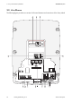
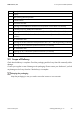
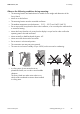
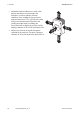
Table Of Contents
- 1 Information on this Manual
- 2 Sunny Island 4548-US/6048-US
- 3 Safety Precautions
- 4 Assembly
- 5 Opening and Closing
- 6 Electrical Connection
- 7 Control Elements
- 8 Initial Start-Up
- 9 Switching On and Off
- 10 Operation
- 11 Archiving Data on an SD Card
- 12 Additional Functions
- 12.1 Load Shedding
- 12.2 Sleep Mode
- 12.3 Time-Controlled Operation
- 12.4 Overload and Short-Circuit Behavior
- 12.5 Mixed Operation with Sunny Island inverters of Different Power
- 12.6 Device Faults and Autostart
- 12.7 Automatic Frequency Synchronization
- 12.8 Time-Controlled Standby
- 12.9 Behavior in the Event of a Failure in a Three-Phase System
- 13 Battery Management
- 14 Connecting External Sources
- 14.1 Generator
- 14.1.1 Parallel Connection
- 14.1.2 Generator Start Options
- 14.1.3 Generator Operation
- 14.1.4 Manual Generator Operation
- 14.1.5 Automatic Generator Operation
- 14.1.6 Limits and Power Control
- 14.1.7 Run Times
- 14.1.8 Operation Together with PV Inverters and Wind Power Inverters
- 14.1.9 Stopping the Generator
- 14.1.10 Stopping the Sunny Island
- 14.1.11 Disturbances
- 14.2 Grid
- 14.2.1 Limits of the Voltage Range and Frequency Range
- 14.2.2 Starting the Sunny Island
- 14.2.3 Operation in the Event of Grid Failure in a Grid-Tie Backup Configuration
- 14.2.4 Backup Operation and Anti-Islanding
- 14.2.5 Grid Reconnection
- 14.2.6 Grid Operation
- 14.2.7 Grid Failure
- 14.2.8 Disturbances
- 14.2.9 Limits and Power Control
- 14.2.10 Operation Together with PV Inverters and Wind Power Inverters
- 14.3 Generator and Grid
- 14.1 Generator
- 15 Relays
- 16 Multicluster Operation
- 16.1 Communication between the Sunny Island inverters
- 16.2 Initial Start-Up of the Multicluster System
- 16.3 Switching a Multicluster System On and Off
- 16.4 Generator Operation
- 16.5 Behavior with Different States of Charge
- 16.6 Testing the Multicluster Communication
- 16.7 Automatic Frequency Synchronization
- 16.8 Updating the Firmware
- 16.9 Error Handling in the Multicluster System
- 16.10 Grid Operation
- 16.11 Generator Emergency Operation
- 17 PV Inverters
- 18 Maintenance and Care
- 19 Parameter Lists
- 20 Troubleshooting
- 21 Accessories
- 22 Technical Data
- 23 Glossary
- 24 Contact
SMA America, LLC 2 Sunny Island 4548-US/6048-US
Technical description SI4548_6048-US-TB_en-13 25
2.4 Required Tools and Resources
The following tools and materials are required in order to mount and install the
Sunny Island 4548-US/6048-US:
2.5 Identifying the Sunny Island
Identify the Sunny Island by the serial number (Serial No.) and the device type (Type) on the type
label. The type label is located on the right-hand side of the enclosure.
Tools (not included in scope of delivery)
Cable knife
Combination pliers
Crimping tool for bootlace ferrules (suitable for cable cross-sections up to 3/0 AWG)
Diagonal cutting pliers
Drill
Drill bit (e.g. for masonry or wood), fastener
3
/
8
in. or Ø 10 mm
Flat-blade screwdriver
3
⁄
32
in. (2.5 mm)
Flat-blade screwdriver SZS 1.0 x 6.5
Allen key
1
⁄
8
in. to
5
⁄
16
in. (3 mm to 8 mm)
Multimeter
Open-end/box wrenches or socket wrenches in the sizes 10/19/24/30
Philips screwdriver, PH1 and PH2
Spirit level
Torque wrench 4 ft-lbs. to 21 ft-lbs. (6 Nm to 28 Nm) with hexagon socket screwdriver bit in the sizes
3
⁄
16
in. (5 mm) and
3
⁄
8
in. (10 mm)
Torque wrench 5 in-lbs. to 22 in-lbs. (0.56 Nm to 2.5 Nm) with flat-blade screwdriver bits in the sizes
3
⁄
32
in. (2.5 mm) and flat-blade screwdriver SZS 1.0 x 6.5
Insulation stripping tool
Material (not included in scope of delivery)
Cable tie
Heat-shrink tubing
Hexagon screws,
5
/
16
in. x 2
3
/
8
in. (8 mm x 60 mm)
Washers
Screw anchor for the wall mounting bracket (e.g. SX 10)
Bootlace ferrules appropriate for the selected cable (see Section 6 "Electrical Connection", page 37)