
SI4548-US-10 Manual
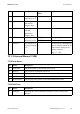

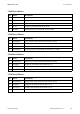
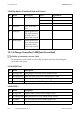


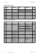
Table Of Contents
- 1 Information on this Manual
- 2 Sunny Island 4548-US/6048-US
- 3 Safety Precautions
- 4 Assembly
- 5 Opening and Closing
- 6 Electrical Connection
- 7 Control Elements
- 8 Initial Start-Up
- 9 Switching On and Off
- 10 Operation
- 11 Archiving Data on an SD Card
- 12 Additional Functions
- 12.1 Load Shedding
- 12.2 Sleep Mode
- 12.3 Time-Controlled Operation
- 12.4 Overload and Short-Circuit Behavior
- 12.5 Mixed Operation with Sunny Island inverters of Different Power
- 12.6 Device Faults and Autostart
- 12.7 Automatic Frequency Synchronization
- 12.8 Time-Controlled Standby
- 12.9 Behavior in the Event of a Failure in a Three-Phase System
- 13 Battery Management
- 14 Connecting External Sources
- 14.1 Generator
- 14.1.1 Parallel Connection
- 14.1.2 Generator Start Options
- 14.1.3 Generator Operation
- 14.1.4 Manual Generator Operation
- 14.1.5 Automatic Generator Operation
- 14.1.6 Limits and Power Control
- 14.1.7 Run Times
- 14.1.8 Operation Together with PV Inverters and Wind Power Inverters
- 14.1.9 Stopping the Generator
- 14.1.10 Stopping the Sunny Island
- 14.1.11 Disturbances
- 14.2 Grid
- 14.2.1 Limits of the Voltage Range and Frequency Range
- 14.2.2 Starting the Sunny Island
- 14.2.3 Operation in the Event of Grid Failure in a Grid-Tie Backup Configuration
- 14.2.4 Backup Operation and Anti-Islanding
- 14.2.5 Grid Reconnection
- 14.2.6 Grid Operation
- 14.2.7 Grid Failure
- 14.2.8 Disturbances
- 14.2.9 Limits and Power Control
- 14.2.10 Operation Together with PV Inverters and Wind Power Inverters
- 14.3 Generator and Grid
- 14.1 Generator
- 15 Relays
- 16 Multicluster Operation
- 16.1 Communication between the Sunny Island inverters
- 16.2 Initial Start-Up of the Multicluster System
- 16.3 Switching a Multicluster System On and Off
- 16.4 Generator Operation
- 16.5 Behavior with Different States of Charge
- 16.6 Testing the Multicluster Communication
- 16.7 Automatic Frequency Synchronization
- 16.8 Updating the Firmware
- 16.9 Error Handling in the Multicluster System
- 16.10 Grid Operation
- 16.11 Generator Emergency Operation
- 17 PV Inverters
- 18 Maintenance and Care
- 19 Parameter Lists
- 20 Troubleshooting
- 21 Accessories
- 22 Technical Data
- 23 Glossary
- 24 Contact

19 Parameter Lists SMA America, LLC
164 SI4548_6048-US-TB_en-13 Technical description
138# Chp Meters (Combined Heat and Power)
19.1.4 Charge Controller (140#)(not UL-certified)
141# SIC50 Total
142# SIC50 1
No. Name Description Value Explanation
01 ChpStt State of CHP plant Idle Off
Run Operation
Lock Locked after operation
02 ChpPwrAt Power of the CHP
plant
03 ChpRmgTm Remaining time of the
CHP plant (minimum
run time) in hours,
minutes and seconds
04 ChpStrRmgTm Remaining time of the
power request of the
CHP plant in hours,
minutes and seconds
Visibility of parameters in menu 140#
The parameters in menu 140# are only visible, if at least one Sunny Island Charger is
connected to the system.
No. Name Description
01 TotSicEgyCntIn Total energy of all Sunny Island Chargers in kWh
02
TotSicDyEgyCntIn
Total daily yield of all Sunny Island Chargers in kWh
03 TotSicPvPwr Total PV power of all Sunny Island Chargers in W
04 TotSicBatCur Total battery current of all Sunny Island Chargers in A
No. Name Description
01 Sic1EgyCntIn Energy of the first Sunny Island Charger in kWh
02
Sic1TdyEgyCntIn
Daily yield of the first Sunny Island Charger in kWh
03 Sic1PvPwr PV power of the first Sunny Island Charger in W
04 Sic1PvVtg PV voltage of the first Sunny Island Charger in V