
SI4548-US-10 Manual

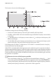


Table Of Contents
- 1 Information on this Manual
- 2 Sunny Island 4548-US/6048-US
- 3 Safety Precautions
- 4 Assembly
- 5 Opening and Closing
- 6 Electrical Connection
- 7 Control Elements
- 8 Initial Start-Up
- 9 Switching On and Off
- 10 Operation
- 11 Archiving Data on an SD Card
- 12 Additional Functions
- 12.1 Load Shedding
- 12.2 Sleep Mode
- 12.3 Time-Controlled Operation
- 12.4 Overload and Short-Circuit Behavior
- 12.5 Mixed Operation with Sunny Island inverters of Different Power
- 12.6 Device Faults and Autostart
- 12.7 Automatic Frequency Synchronization
- 12.8 Time-Controlled Standby
- 12.9 Behavior in the Event of a Failure in a Three-Phase System
- 13 Battery Management
- 14 Connecting External Sources
- 14.1 Generator
- 14.1.1 Parallel Connection
- 14.1.2 Generator Start Options
- 14.1.3 Generator Operation
- 14.1.4 Manual Generator Operation
- 14.1.5 Automatic Generator Operation
- 14.1.6 Limits and Power Control
- 14.1.7 Run Times
- 14.1.8 Operation Together with PV Inverters and Wind Power Inverters
- 14.1.9 Stopping the Generator
- 14.1.10 Stopping the Sunny Island
- 14.1.11 Disturbances
- 14.2 Grid
- 14.2.1 Limits of the Voltage Range and Frequency Range
- 14.2.2 Starting the Sunny Island
- 14.2.3 Operation in the Event of Grid Failure in a Grid-Tie Backup Configuration
- 14.2.4 Backup Operation and Anti-Islanding
- 14.2.5 Grid Reconnection
- 14.2.6 Grid Operation
- 14.2.7 Grid Failure
- 14.2.8 Disturbances
- 14.2.9 Limits and Power Control
- 14.2.10 Operation Together with PV Inverters and Wind Power Inverters
- 14.3 Generator and Grid
- 14.1 Generator
- 15 Relays
- 16 Multicluster Operation
- 16.1 Communication between the Sunny Island inverters
- 16.2 Initial Start-Up of the Multicluster System
- 16.3 Switching a Multicluster System On and Off
- 16.4 Generator Operation
- 16.5 Behavior with Different States of Charge
- 16.6 Testing the Multicluster Communication
- 16.7 Automatic Frequency Synchronization
- 16.8 Updating the Firmware
- 16.9 Error Handling in the Multicluster System
- 16.10 Grid Operation
- 16.11 Generator Emergency Operation
- 17 PV Inverters
- 18 Maintenance and Care
- 19 Parameter Lists
- 20 Troubleshooting
- 21 Accessories
- 22 Technical Data
- 23 Glossary
- 24 Contact

SMA America, LLC 17 PV Inverters
Technical description SI4548_6048-US-TB_en-13 155
This function is shown in the following figure:
The different settings have the following meanings:
•f
0
refers to the base frequency of the micro grid created by the Sunny Island.
•f
AC
Delta– and f
AC
Delta+ refer to the maximum range in which the Sunny Boy is active relative
to f
0
, 60 Hz.
•f
AC
Start delta refers to the frequency increase relative to f
0
, at which point the frequency shift
power control begins
•f
AC
Limit delta refers to the frequency increase relative to f
0
, at which point the frequency shift
power control stops. The power of the Sunny Boy at this point is 0 W.
If the limiting value "f
AC
Delta–" is fallen below or if "f
AC
Delta+" is exceeded, then the Sunny Boy
inverters disconnect from the utility grid.
When FSPC is activated and the diesel generator in the stand-alone grid is in operation, the diesel
generator determines the frequency, and the Sunny Boy inverters react to certain changes in the diesel
generator frequency. The diesel generators generally operate at 60 Hz under load. For this reason,
in most cases the Sunny Boy inverters will deliver their entire power to the stand-alone grid, even when
the generator is in operation.
Short-term increase of the frequency possible
If the current battery voltage (V
Bat
) is greater than the nominal battery voltage (V
Bat, nom
) and
is also to be synchronized with an external source (generator), the Sunny Island temporarily
increases the frequency and disconnects the Sunny Boy inverters using the frequency shutdown
method (overfrequency). Afterwards, it synchronizes with the generator.