
SI4548-US-10 Manual

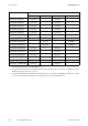
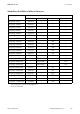
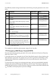
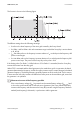
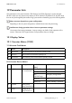


Table Of Contents
- 1 Information on this Manual
- 2 Sunny Island 4548-US/6048-US
- 3 Safety Precautions
- 4 Assembly
- 5 Opening and Closing
- 6 Electrical Connection
- 7 Control Elements
- 8 Initial Start-Up
- 9 Switching On and Off
- 10 Operation
- 11 Archiving Data on an SD Card
- 12 Additional Functions
- 12.1 Load Shedding
- 12.2 Sleep Mode
- 12.3 Time-Controlled Operation
- 12.4 Overload and Short-Circuit Behavior
- 12.5 Mixed Operation with Sunny Island inverters of Different Power
- 12.6 Device Faults and Autostart
- 12.7 Automatic Frequency Synchronization
- 12.8 Time-Controlled Standby
- 12.9 Behavior in the Event of a Failure in a Three-Phase System
- 13 Battery Management
- 14 Connecting External Sources
- 14.1 Generator
- 14.1.1 Parallel Connection
- 14.1.2 Generator Start Options
- 14.1.3 Generator Operation
- 14.1.4 Manual Generator Operation
- 14.1.5 Automatic Generator Operation
- 14.1.6 Limits and Power Control
- 14.1.7 Run Times
- 14.1.8 Operation Together with PV Inverters and Wind Power Inverters
- 14.1.9 Stopping the Generator
- 14.1.10 Stopping the Sunny Island
- 14.1.11 Disturbances
- 14.2 Grid
- 14.2.1 Limits of the Voltage Range and Frequency Range
- 14.2.2 Starting the Sunny Island
- 14.2.3 Operation in the Event of Grid Failure in a Grid-Tie Backup Configuration
- 14.2.4 Backup Operation and Anti-Islanding
- 14.2.5 Grid Reconnection
- 14.2.6 Grid Operation
- 14.2.7 Grid Failure
- 14.2.8 Disturbances
- 14.2.9 Limits and Power Control
- 14.2.10 Operation Together with PV Inverters and Wind Power Inverters
- 14.3 Generator and Grid
- 14.1 Generator
- 15 Relays
- 16 Multicluster Operation
- 16.1 Communication between the Sunny Island inverters
- 16.2 Initial Start-Up of the Multicluster System
- 16.3 Switching a Multicluster System On and Off
- 16.4 Generator Operation
- 16.5 Behavior with Different States of Charge
- 16.6 Testing the Multicluster Communication
- 16.7 Automatic Frequency Synchronization
- 16.8 Updating the Firmware
- 16.9 Error Handling in the Multicluster System
- 16.10 Grid Operation
- 16.11 Generator Emergency Operation
- 17 PV Inverters
- 18 Maintenance and Care
- 19 Parameter Lists
- 20 Troubleshooting
- 21 Accessories
- 22 Technical Data
- 23 Glossary
- 24 Contact

17 PV Inverters SMA America, LLC
154 SI4548_6048-US-TB_en-13 Technical description
The "OffGrid" parameter setting automatically sets the following Sunny Boy parameters to the values
below:
This completes the stand-alone grid parameter settings for the Sunny Boy.
17.5 Frequency-Shift Power Control (FSPC)
This section describes the operating principles of the "power adjustment via frequency" (Frequency
Shift Power Control - FSPC).
If Sunny Boy inverters are connected to the AC side of the off-grid system, the Sunny Island must be
able to limit their output power. This situation can occur when, e.g. the Sunny Island battery is fully
charged and the (solar) power available from the PV array exceeds the power required by the
connected loads.
To prevent the excess energy from overcharging the battery, the Sunny Island 4548-US/6048-US
recognizes this situation and changes the frequency at the AC output. This frequency adjustment is
analyzed by the Sunny Boy. As soon as the power frequency increases and exceeds a defined value
"f
AC
Start Delta", the Sunny Boy limits its power accordingly.
No. Parameter Short descr. Value
1 Test current mA Off (MSD = 0)
2 Vac.Min V –12% V
AC Nom
*
*V
AC Nom
= 208 V/240 V/277 V
3 Vac.Max V +10% V
AC Nom*
4 Fac-delta–
Lower range in which the Sunny Boy is active
relative to f
0
Hz –3.0 (starting from the
base frequency f
0
)
5 Fac-max+
Upper range, where the Sunny Boy is active,
based on f
0
Hz +3.0 (starting at the
base frequency f
0
)
6 dFac-Max
max. rate of change
Hz/s 4
7 Fac-start delta
Frequency increase in relation to f
0
, at which
point the power control via frequency begins
Hz 1 (starting from the
base frequency f
0
)
8 Fac-Limit delta
Frequency increase based on f
0
, where the
power control via frequency ends. The power of
the Sunny Boy at this point is 0 W.
Hz 2 (starting from the
base frequency f
0
)