
SI4548-US-10 Manual

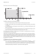


Table Of Contents
- 1 Information on this Manual
- 2 Sunny Island 4548-US/6048-US
- 3 Safety Precautions
- 4 Assembly
- 5 Opening and Closing
- 6 Electrical Connection
- 7 Control Elements
- 8 Initial Start-Up
- 9 Switching On and Off
- 10 Operation
- 11 Archiving Data on an SD Card
- 12 Additional Functions
- 12.1 Load Shedding
- 12.2 Sleep Mode
- 12.3 Time-Controlled Operation
- 12.4 Overload and Short-Circuit Behavior
- 12.5 Mixed Operation with Sunny Island inverters of Different Power
- 12.6 Device Faults and Autostart
- 12.7 Automatic Frequency Synchronization
- 12.8 Time-Controlled Standby
- 12.9 Behavior in the Event of a Failure in a Three-Phase System
- 13 Battery Management
- 14 Connecting External Sources
- 14.1 Generator
- 14.1.1 Parallel Connection
- 14.1.2 Generator Start Options
- 14.1.3 Generator Operation
- 14.1.4 Manual Generator Operation
- 14.1.5 Automatic Generator Operation
- 14.1.6 Limits and Power Control
- 14.1.7 Run Times
- 14.1.8 Operation Together with PV Inverters and Wind Power Inverters
- 14.1.9 Stopping the Generator
- 14.1.10 Stopping the Sunny Island
- 14.1.11 Disturbances
- 14.2 Grid
- 14.2.1 Limits of the Voltage Range and Frequency Range
- 14.2.2 Starting the Sunny Island
- 14.2.3 Operation in the Event of Grid Failure in a Grid-Tie Backup Configuration
- 14.2.4 Backup Operation and Anti-Islanding
- 14.2.5 Grid Reconnection
- 14.2.6 Grid Operation
- 14.2.7 Grid Failure
- 14.2.8 Disturbances
- 14.2.9 Limits and Power Control
- 14.2.10 Operation Together with PV Inverters and Wind Power Inverters
- 14.3 Generator and Grid
- 14.1 Generator
- 15 Relays
- 16 Multicluster Operation
- 16.1 Communication between the Sunny Island inverters
- 16.2 Initial Start-Up of the Multicluster System
- 16.3 Switching a Multicluster System On and Off
- 16.4 Generator Operation
- 16.5 Behavior with Different States of Charge
- 16.6 Testing the Multicluster Communication
- 16.7 Automatic Frequency Synchronization
- 16.8 Updating the Firmware
- 16.9 Error Handling in the Multicluster System
- 16.10 Grid Operation
- 16.11 Generator Emergency Operation
- 17 PV Inverters
- 18 Maintenance and Care
- 19 Parameter Lists
- 20 Troubleshooting
- 21 Accessories
- 22 Technical Data
- 23 Glossary
- 24 Contact

SMA America, LLC 17 PV Inverters
Technical description SI4548_6048-US-TB_en-13 151
17.2 Setting of the Off-Grid Parameter
Controlled battery charging is needed in an off-grid configuration. Therefore Sunny Boy inverters can
reduce their feed-in power. This task is performed by an implemented "Frequency Shift Power Control"
system (see Section 17.5 "Frequency-Shift Power Control (FSPC)", page 154).
To activate this function, you must first pre-configure the Sunny Boy via programming.
17.3 Configuration
In order to adjust the parameters of the Sunny Boy, you need a connection to a communication
device. Install one of these three variants:
•Sunny WebBox
• Sunny Boy Control
• Computer with the Sunny Data/Sunny Data Control software and with service cable for data
transmission (SMA order number: "USBPBS-11" ‒ USB service interface)
17.4 Sunny Boy Parameter Settings
You will find the latest information in the download area at www.SMA-America.com in the technical
information "PV Inverters–Use of PV inverters in off-grid systems and backup systems in North and
South America".
Grid-tied
When the Sunny Island is used in a backup system, the parameter "Backupmode" for all Sunny Boy
inverters in that system must be set to OnAll. This allows the Sunny Island to switch the "Default"
parameter on the Sunny Boy from UL1741 to Offgrid. However, this adjustment can only occur if
there is a RS485 communication bus set up between the inverters and they each have an RS485 card.
You can test that the communication bus is working by looking at the Sunny Boy display. When the
utility grid is present at the AC2 terminal of the Sunny Island, the Sunny Boy will display the message
"Backupstate: Grid". When there is no utility grid present at the AC2 terminal of the Sunny Island, the
Sunny Boy will display the message "Backupstate: Off-Grid". The RS485 communication bus needs
to be verified if this change does not occur.
Danger to life due to backfeed into the utility grid in the event of grid failure.
Once you set the Sunny Boy to stand-alone grid parameters, the device no longer complies with
IEEE 929 and the IEEE 1547.
• Observe the locally applicable regulations.
• Consult the responsible power supply company.