
SI4548-US-10 Manual
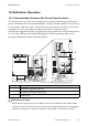
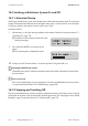
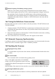
Table Of Contents
- 1 Information on this Manual
- 2 Sunny Island 4548-US/6048-US
- 3 Safety Precautions
- 4 Assembly
- 5 Opening and Closing
- 6 Electrical Connection
- 7 Control Elements
- 8 Initial Start-Up
- 9 Switching On and Off
- 10 Operation
- 11 Archiving Data on an SD Card
- 12 Additional Functions
- 12.1 Load Shedding
- 12.2 Sleep Mode
- 12.3 Time-Controlled Operation
- 12.4 Overload and Short-Circuit Behavior
- 12.5 Mixed Operation with Sunny Island inverters of Different Power
- 12.6 Device Faults and Autostart
- 12.7 Automatic Frequency Synchronization
- 12.8 Time-Controlled Standby
- 12.9 Behavior in the Event of a Failure in a Three-Phase System
- 13 Battery Management
- 14 Connecting External Sources
- 14.1 Generator
- 14.1.1 Parallel Connection
- 14.1.2 Generator Start Options
- 14.1.3 Generator Operation
- 14.1.4 Manual Generator Operation
- 14.1.5 Automatic Generator Operation
- 14.1.6 Limits and Power Control
- 14.1.7 Run Times
- 14.1.8 Operation Together with PV Inverters and Wind Power Inverters
- 14.1.9 Stopping the Generator
- 14.1.10 Stopping the Sunny Island
- 14.1.11 Disturbances
- 14.2 Grid
- 14.2.1 Limits of the Voltage Range and Frequency Range
- 14.2.2 Starting the Sunny Island
- 14.2.3 Operation in the Event of Grid Failure in a Grid-Tie Backup Configuration
- 14.2.4 Backup Operation and Anti-Islanding
- 14.2.5 Grid Reconnection
- 14.2.6 Grid Operation
- 14.2.7 Grid Failure
- 14.2.8 Disturbances
- 14.2.9 Limits and Power Control
- 14.2.10 Operation Together with PV Inverters and Wind Power Inverters
- 14.3 Generator and Grid
- 14.1 Generator
- 15 Relays
- 16 Multicluster Operation
- 16.1 Communication between the Sunny Island inverters
- 16.2 Initial Start-Up of the Multicluster System
- 16.3 Switching a Multicluster System On and Off
- 16.4 Generator Operation
- 16.5 Behavior with Different States of Charge
- 16.6 Testing the Multicluster Communication
- 16.7 Automatic Frequency Synchronization
- 16.8 Updating the Firmware
- 16.9 Error Handling in the Multicluster System
- 16.10 Grid Operation
- 16.11 Generator Emergency Operation
- 17 PV Inverters
- 18 Maintenance and Care
- 19 Parameter Lists
- 20 Troubleshooting
- 21 Accessories
- 22 Technical Data
- 23 Glossary
- 24 Contact

SMA America, LLC 16 Multicluster Operation
Technical description SI4548_6048-US-TB_en-13 147
16.3.3 Load Shedding in a Multicluster System
The load-shedding contactor in the Multicluster Box is controlled depending on the state of charge of
the batteries.
Significance of the SOC limiting values:
When the state of charge of a battery reaches the lower SOC limiting value, the load-shedding
contactor is opened. The state of charge of the battery of the main cluster and the states of charge of
the batteries of the extension clusters are evaluated. The load-shedding contactor disconnects the
loads from the stand-alone grid. When the state of charge of all batteries reaches the upper SOC
limiting value during recharging, the load-shedding contactor closes. The load-shedding contactor
connects the loads to the stand-alone grid.
The load shedding of the Multicluster Box only reacts to the SOC value of the main cluster.
1. Select the parameter "242.01 Lod1SocTm1Str" set to the lower SOC limiting value.
2. Select the parameter "242.02 Lod1SocTm1Stp" set to the upper SOC limiting value. The upper
SOC limiting value must be at least 10 percentage points above the lower SOC limiting value.
3. Set the parameter "242.05 Lod1Tm1Str" and the parameter "242.06 Lod1Tm2Str" each to the
same value, e.g. to 000000. This will switch the time-dependent load shedding off.
16.4 Generator Operation
The generator request of the main master comprises its own request (based on SOC, time, etc.) and
possible requests from one or more extension clusters. The generator remains in a requested state as
long as a request is present.
16.5 Behavior with Different States of Charge
In Multicluster systems, each cluster has its own battery storage system. To prevent the states of charge
of the various battery storage systems from diverging over time, a function for equalization of the
states of charge is integrated into the Sunny Island devices. This distributes the power to all clusters,
however, it is not always distributed identically. Instead, the cluster with the highest state of charge
discharges the most power or charges the battery with the lowest power.
The differences in power depend on the difference in the state of charge and total 1% of the nominal
power for each 1% of difference in the state of charge. Thus, when initial charge states differ,
equalization of the states of charge over the course of time is ensured. If all batteries in the various
clusters have the same capacity, the charge states should always be within a few percent of each
other. Only if a fault occurs, or upon deliberate deactivation of individual clusters, can a greater
imbalance arise, but even so, such an imbalance should also be equalized after one day at the latest.
Generator request
The determined generator request at the extension clusters is transferred to the main master via
a communication connection.