
SI4548-US-10 Manual
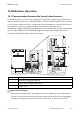
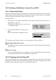
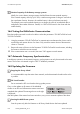
Table Of Contents
- 1 Information on this Manual
- 2 Sunny Island 4548-US/6048-US
- 3 Safety Precautions
- 4 Assembly
- 5 Opening and Closing
- 6 Electrical Connection
- 7 Control Elements
- 8 Initial Start-Up
- 9 Switching On and Off
- 10 Operation
- 11 Archiving Data on an SD Card
- 12 Additional Functions
- 12.1 Load Shedding
- 12.2 Sleep Mode
- 12.3 Time-Controlled Operation
- 12.4 Overload and Short-Circuit Behavior
- 12.5 Mixed Operation with Sunny Island inverters of Different Power
- 12.6 Device Faults and Autostart
- 12.7 Automatic Frequency Synchronization
- 12.8 Time-Controlled Standby
- 12.9 Behavior in the Event of a Failure in a Three-Phase System
- 13 Battery Management
- 14 Connecting External Sources
- 14.1 Generator
- 14.1.1 Parallel Connection
- 14.1.2 Generator Start Options
- 14.1.3 Generator Operation
- 14.1.4 Manual Generator Operation
- 14.1.5 Automatic Generator Operation
- 14.1.6 Limits and Power Control
- 14.1.7 Run Times
- 14.1.8 Operation Together with PV Inverters and Wind Power Inverters
- 14.1.9 Stopping the Generator
- 14.1.10 Stopping the Sunny Island
- 14.1.11 Disturbances
- 14.2 Grid
- 14.2.1 Limits of the Voltage Range and Frequency Range
- 14.2.2 Starting the Sunny Island
- 14.2.3 Operation in the Event of Grid Failure in a Grid-Tie Backup Configuration
- 14.2.4 Backup Operation and Anti-Islanding
- 14.2.5 Grid Reconnection
- 14.2.6 Grid Operation
- 14.2.7 Grid Failure
- 14.2.8 Disturbances
- 14.2.9 Limits and Power Control
- 14.2.10 Operation Together with PV Inverters and Wind Power Inverters
- 14.3 Generator and Grid
- 14.1 Generator
- 15 Relays
- 16 Multicluster Operation
- 16.1 Communication between the Sunny Island inverters
- 16.2 Initial Start-Up of the Multicluster System
- 16.3 Switching a Multicluster System On and Off
- 16.4 Generator Operation
- 16.5 Behavior with Different States of Charge
- 16.6 Testing the Multicluster Communication
- 16.7 Automatic Frequency Synchronization
- 16.8 Updating the Firmware
- 16.9 Error Handling in the Multicluster System
- 16.10 Grid Operation
- 16.11 Generator Emergency Operation
- 17 PV Inverters
- 18 Maintenance and Care
- 19 Parameter Lists
- 20 Troubleshooting
- 21 Accessories
- 22 Technical Data
- 23 Glossary
- 24 Contact

SMA America, LLC 16 Multicluster Operation
Technical description SI4548_6048-US-TB_en-13 145
16.2 Initial Start-Up of the Multicluster System
1. Perform steps 1 to 3 of the QCG start (see Section 8.2 "Starting the Quick Configuration Guide
(QCG)", page 67).
2. At "New System" set the following parameters:
– Device type (master, slave 1, slave 2, slave 3)
– System configuration (3Phase, 1Phase 1, 1Phase 2, 1Phase 3, 2Phase 2, 2Phase 4,
MC-Box), for multicluster operation choose "MC-Box". Default setting: "1Phase 1"
– Multicluster configuration (MainCluster, ExtensionClst1, ExtensionClst2, ExtensionClst3),
default setting is "MainCluster"
– Device type of the Multicluster Box (MC-12), default setting: "MC-Box-12"
3. For further settings, follow the QCG instructions (see Section 8.2 "Starting the Quick
Configuration Guide (QCG)", page 67).
Possible load shedding during initial start-up of a multicluster system
Unwanted load shedding can occur during the initial start-up of a multicluster system. The
possible causes of this can be a too-low state of charge of the battery or a still too inaccurate
charge level calculation in the Sunny Island.
• Disconnect all loads before the initial start-up of a multicluster system.
• After initial start-up, observe the SOC on the master of the main cluster via the parameter
"120.01 BatSoc". As soon as the SOC has risen above 50%, connect the loads.