
SI4548-US-10 Manual
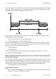
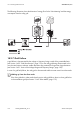
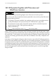
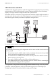
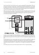
Table Of Contents
- 1 Information on this Manual
- 2 Sunny Island 4548-US/6048-US
- 3 Safety Precautions
- 4 Assembly
- 5 Opening and Closing
- 6 Electrical Connection
- 7 Control Elements
- 8 Initial Start-Up
- 9 Switching On and Off
- 10 Operation
- 11 Archiving Data on an SD Card
- 12 Additional Functions
- 12.1 Load Shedding
- 12.2 Sleep Mode
- 12.3 Time-Controlled Operation
- 12.4 Overload and Short-Circuit Behavior
- 12.5 Mixed Operation with Sunny Island inverters of Different Power
- 12.6 Device Faults and Autostart
- 12.7 Automatic Frequency Synchronization
- 12.8 Time-Controlled Standby
- 12.9 Behavior in the Event of a Failure in a Three-Phase System
- 13 Battery Management
- 14 Connecting External Sources
- 14.1 Generator
- 14.1.1 Parallel Connection
- 14.1.2 Generator Start Options
- 14.1.3 Generator Operation
- 14.1.4 Manual Generator Operation
- 14.1.5 Automatic Generator Operation
- 14.1.6 Limits and Power Control
- 14.1.7 Run Times
- 14.1.8 Operation Together with PV Inverters and Wind Power Inverters
- 14.1.9 Stopping the Generator
- 14.1.10 Stopping the Sunny Island
- 14.1.11 Disturbances
- 14.2 Grid
- 14.2.1 Limits of the Voltage Range and Frequency Range
- 14.2.2 Starting the Sunny Island
- 14.2.3 Operation in the Event of Grid Failure in a Grid-Tie Backup Configuration
- 14.2.4 Backup Operation and Anti-Islanding
- 14.2.5 Grid Reconnection
- 14.2.6 Grid Operation
- 14.2.7 Grid Failure
- 14.2.8 Disturbances
- 14.2.9 Limits and Power Control
- 14.2.10 Operation Together with PV Inverters and Wind Power Inverters
- 14.3 Generator and Grid
- 14.1 Generator
- 15 Relays
- 16 Multicluster Operation
- 16.1 Communication between the Sunny Island inverters
- 16.2 Initial Start-Up of the Multicluster System
- 16.3 Switching a Multicluster System On and Off
- 16.4 Generator Operation
- 16.5 Behavior with Different States of Charge
- 16.6 Testing the Multicluster Communication
- 16.7 Automatic Frequency Synchronization
- 16.8 Updating the Firmware
- 16.9 Error Handling in the Multicluster System
- 16.10 Grid Operation
- 16.11 Generator Emergency Operation
- 17 PV Inverters
- 18 Maintenance and Care
- 19 Parameter Lists
- 20 Troubleshooting
- 21 Accessories
- 22 Technical Data
- 23 Glossary
- 24 Contact

14 Connecting External Sources SMA America, LLC
138 SI4548_6048-US-TB_en-13 Technical description
The Sunny Island has one AC external source connection labeled AC2 Grid/Generator. With only
one external connection, the DigIn input is used to distinguish between the generator or line voltage.
If the DigIn input detects an open electric circuit, the Sunny Island is operated with grid parameters
and can feed excess electric current into the utility grid. When the DigIn input has a closed electric
circuit the Sunny Island recognizes that a generator is available.
When using a generator, install a transfer switch which switches from grid to generator. This can be
an automatic transfer switch (ATS) or a manual transfer switch. An automatic transfer switch provides
an automatic changeover between generator and utility grid. In the event of a grid failure, no
intervention by the operator is necessary.
In order to switch the signal circuit via the DigIn input, a single pole break contact or a single pole
auxiliary relay with a 120 V coil is necessary. If there is no auxiliary relay present in the ATS, you must
install an external contactor with a 120 V or 240 V coil. The coil is supplied with voltage via the utility
grid.
Treat this electric circuit as a communication circuit, and do not run this in parallel to AC voltage and
current cables. Running this circuit parallel to AC voltage and current conductors may cause
interference in the signal and give the Sunny Island an incorrect signal. No voltage should be present
on the relay during a grid failure. For external relays, pull voltage from the grid side of the transfer
switch.
The auxiliary relay can be a part of the automatic transfer switch or a separate assembly.