
SI4548-US-10 Manual
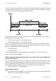
Table Of Contents
- 1 Information on this Manual
- 2 Sunny Island 4548-US/6048-US
- 3 Safety Precautions
- 4 Assembly
- 5 Opening and Closing
- 6 Electrical Connection
- 7 Control Elements
- 8 Initial Start-Up
- 9 Switching On and Off
- 10 Operation
- 11 Archiving Data on an SD Card
- 12 Additional Functions
- 12.1 Load Shedding
- 12.2 Sleep Mode
- 12.3 Time-Controlled Operation
- 12.4 Overload and Short-Circuit Behavior
- 12.5 Mixed Operation with Sunny Island inverters of Different Power
- 12.6 Device Faults and Autostart
- 12.7 Automatic Frequency Synchronization
- 12.8 Time-Controlled Standby
- 12.9 Behavior in the Event of a Failure in a Three-Phase System
- 13 Battery Management
- 14 Connecting External Sources
- 14.1 Generator
- 14.1.1 Parallel Connection
- 14.1.2 Generator Start Options
- 14.1.3 Generator Operation
- 14.1.4 Manual Generator Operation
- 14.1.5 Automatic Generator Operation
- 14.1.6 Limits and Power Control
- 14.1.7 Run Times
- 14.1.8 Operation Together with PV Inverters and Wind Power Inverters
- 14.1.9 Stopping the Generator
- 14.1.10 Stopping the Sunny Island
- 14.1.11 Disturbances
- 14.2 Grid
- 14.2.1 Limits of the Voltage Range and Frequency Range
- 14.2.2 Starting the Sunny Island
- 14.2.3 Operation in the Event of Grid Failure in a Grid-Tie Backup Configuration
- 14.2.4 Backup Operation and Anti-Islanding
- 14.2.5 Grid Reconnection
- 14.2.6 Grid Operation
- 14.2.7 Grid Failure
- 14.2.8 Disturbances
- 14.2.9 Limits and Power Control
- 14.2.10 Operation Together with PV Inverters and Wind Power Inverters
- 14.3 Generator and Grid
- 14.1 Generator
- 15 Relays
- 16 Multicluster Operation
- 16.1 Communication between the Sunny Island inverters
- 16.2 Initial Start-Up of the Multicluster System
- 16.3 Switching a Multicluster System On and Off
- 16.4 Generator Operation
- 16.5 Behavior with Different States of Charge
- 16.6 Testing the Multicluster Communication
- 16.7 Automatic Frequency Synchronization
- 16.8 Updating the Firmware
- 16.9 Error Handling in the Multicluster System
- 16.10 Grid Operation
- 16.11 Generator Emergency Operation
- 17 PV Inverters
- 18 Maintenance and Care
- 19 Parameter Lists
- 20 Troubleshooting
- 21 Accessories
- 22 Technical Data
- 23 Glossary
- 24 Contact

SMA America, LLC 14 Connecting External Sources
Technical description SI4548_6048-US-TB_en-13 135
14.2.8 Disturbances
Reverse Power
If the defined reverse power ("232.09 GdRvPwr" parameter) is exceeded for the time
"232.10 GdRvTm", the grid is disconnected. After reverse power, connection is blocked for at least
"231.03 ExtLkTm".
Grid Failure
If a grid failure is detected (failure on the master line conductor), the grid is disconnected immediately.
Grid Phase Failure
The failure of a line conductor (e.g. broken fuse) on a slave device is treated as a phase failure.
The slave device then disconnects this line conductor. If the line conductor is detected as being
available again, it is reconnected.
The phase failure on the master device is treated as a grid failure (see above).
Slave Device Failure
If a slave fails, the system continues to operate using the remaining devices of the cluster.
14.2.9 Limits and Power Control
The Sunny Island burdens the grid at each line conductor with the current defined in the parameter
"232.03 GdCurNom". The power that is not directly used by the loads flows into the battery for
charging. At the same time, the limits for the AC charging current limit (parameter "210.02
InvChrgCurMax") on the Sunny Island and the DC charging current limit (parameter "222.01
BatChrgCurMax") are active. If the battery voltage reaches the charging voltage target value, it is
also reduced (see Section 13.4 "Charge Control", page 109).
If the current set using the parameter "232.03 GdCurNom" is not sufficient for powering the loads,
the battery provides support.
Silent mode active
When silent mode is activated, the grid cannot be supported.
The grid may temporarily fail. This way, the voltage supply of the loads will be interrupted for
a short time.