
SI4548-US-10 Manual


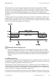


Table Of Contents
- 1 Information on this Manual
- 2 Sunny Island 4548-US/6048-US
- 3 Safety Precautions
- 4 Assembly
- 5 Opening and Closing
- 6 Electrical Connection
- 7 Control Elements
- 8 Initial Start-Up
- 9 Switching On and Off
- 10 Operation
- 11 Archiving Data on an SD Card
- 12 Additional Functions
- 12.1 Load Shedding
- 12.2 Sleep Mode
- 12.3 Time-Controlled Operation
- 12.4 Overload and Short-Circuit Behavior
- 12.5 Mixed Operation with Sunny Island inverters of Different Power
- 12.6 Device Faults and Autostart
- 12.7 Automatic Frequency Synchronization
- 12.8 Time-Controlled Standby
- 12.9 Behavior in the Event of a Failure in a Three-Phase System
- 13 Battery Management
- 14 Connecting External Sources
- 14.1 Generator
- 14.1.1 Parallel Connection
- 14.1.2 Generator Start Options
- 14.1.3 Generator Operation
- 14.1.4 Manual Generator Operation
- 14.1.5 Automatic Generator Operation
- 14.1.6 Limits and Power Control
- 14.1.7 Run Times
- 14.1.8 Operation Together with PV Inverters and Wind Power Inverters
- 14.1.9 Stopping the Generator
- 14.1.10 Stopping the Sunny Island
- 14.1.11 Disturbances
- 14.2 Grid
- 14.2.1 Limits of the Voltage Range and Frequency Range
- 14.2.2 Starting the Sunny Island
- 14.2.3 Operation in the Event of Grid Failure in a Grid-Tie Backup Configuration
- 14.2.4 Backup Operation and Anti-Islanding
- 14.2.5 Grid Reconnection
- 14.2.6 Grid Operation
- 14.2.7 Grid Failure
- 14.2.8 Disturbances
- 14.2.9 Limits and Power Control
- 14.2.10 Operation Together with PV Inverters and Wind Power Inverters
- 14.3 Generator and Grid
- 14.1 Generator
- 15 Relays
- 16 Multicluster Operation
- 16.1 Communication between the Sunny Island inverters
- 16.2 Initial Start-Up of the Multicluster System
- 16.3 Switching a Multicluster System On and Off
- 16.4 Generator Operation
- 16.5 Behavior with Different States of Charge
- 16.6 Testing the Multicluster Communication
- 16.7 Automatic Frequency Synchronization
- 16.8 Updating the Firmware
- 16.9 Error Handling in the Multicluster System
- 16.10 Grid Operation
- 16.11 Generator Emergency Operation
- 17 PV Inverters
- 18 Maintenance and Care
- 19 Parameter Lists
- 20 Troubleshooting
- 21 Accessories
- 22 Technical Data
- 23 Glossary
- 24 Contact

14 Connecting External Sources SMA America, LLC
130 SI4548_6048-US-TB_en-13 Technical description
14.2.1 Limits of the Voltage Range and Frequency Range
In order to operate on the grid, very strict limits (for voltage and frequency) must generally be
maintained. These strict limits are not sensible for generator operation. The limits are therefore set
separately for grid operation and the generator limits are not used.
14.2.2 Starting the Sunny Island
The Sunny Island always starts in stand-alone grid operation. Once the device is operating, it checks
for the presence and validity (voltage and frequency) of the external grid.
14.2.3 Operation in the Event of Grid Failure in a Grid-Tie Backup
Configuration
If the utility grid fails, the Sunny Island supplies the requirements of the protected load switch.
At the same time the Sunny Island serves as the voltage source for Sunny Boy inverters or any other
grid-compatible power source.
If the supply of energy from the power source such as Sunny Boy inverters exceeds the demands of
the protected load switch, the energy surplus will be used by the Sunny Island to charge the batteries.
14.2.4 Backup Operation and Anti-Islanding
In general, Sunny Boy inverters in backup systems are working for feeding energy into the utility grid.
According to UL1741 an Anti-Islanding has to be active. During normal operation, the Sunny Island
performs this verification. The battery inverter is connected to the Sunny Boy via a CAT5 cable using
a RS485 communication. This communication line tells the Sunny Boy that the Sunny Island is active
and monitors the utility grid.
Whenever this information is missing (in the event of maintenance or interference) the Sunny Boy
inverters switch from the "OffGrid" setting to the "grid tied" setting and takes on the anti-islanding
function. This ensures that an anti-islanding is active at all times according to UL1741 when feeding
into the utility grid.
If the Sunny Island continues working, it orders the Sunny Boy inverters to switch back to the "OffGrid"
setting and performs the anti-islanding.
This function can be realized with the Sunny Island inverters in combination with the PV inverters
Sunny Boy 3000US, 3800US, 4000US, 5000US, 6000US, 7000US and 8000US.
RS485 Piggy-Backs must be installed in both the Sunny Island and in the Sunny Boy inverters. In
addition, a CAT5 cable is needed.
Default settings
The default settings for limits during grid operation comply with the following standards:
• For 120 V_60 Hz: UL1741