
SI4548-US-10 Manual


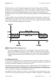


Table Of Contents
- 1 Information on this Manual
- 2 Sunny Island 4548-US/6048-US
- 3 Safety Precautions
- 4 Assembly
- 5 Opening and Closing
- 6 Electrical Connection
- 7 Control Elements
- 8 Initial Start-Up
- 9 Switching On and Off
- 10 Operation
- 11 Archiving Data on an SD Card
- 12 Additional Functions
- 12.1 Load Shedding
- 12.2 Sleep Mode
- 12.3 Time-Controlled Operation
- 12.4 Overload and Short-Circuit Behavior
- 12.5 Mixed Operation with Sunny Island inverters of Different Power
- 12.6 Device Faults and Autostart
- 12.7 Automatic Frequency Synchronization
- 12.8 Time-Controlled Standby
- 12.9 Behavior in the Event of a Failure in a Three-Phase System
- 13 Battery Management
- 14 Connecting External Sources
- 14.1 Generator
- 14.1.1 Parallel Connection
- 14.1.2 Generator Start Options
- 14.1.3 Generator Operation
- 14.1.4 Manual Generator Operation
- 14.1.5 Automatic Generator Operation
- 14.1.6 Limits and Power Control
- 14.1.7 Run Times
- 14.1.8 Operation Together with PV Inverters and Wind Power Inverters
- 14.1.9 Stopping the Generator
- 14.1.10 Stopping the Sunny Island
- 14.1.11 Disturbances
- 14.2 Grid
- 14.2.1 Limits of the Voltage Range and Frequency Range
- 14.2.2 Starting the Sunny Island
- 14.2.3 Operation in the Event of Grid Failure in a Grid-Tie Backup Configuration
- 14.2.4 Backup Operation and Anti-Islanding
- 14.2.5 Grid Reconnection
- 14.2.6 Grid Operation
- 14.2.7 Grid Failure
- 14.2.8 Disturbances
- 14.2.9 Limits and Power Control
- 14.2.10 Operation Together with PV Inverters and Wind Power Inverters
- 14.3 Generator and Grid
- 14.1 Generator
- 15 Relays
- 16 Multicluster Operation
- 16.1 Communication between the Sunny Island inverters
- 16.2 Initial Start-Up of the Multicluster System
- 16.3 Switching a Multicluster System On and Off
- 16.4 Generator Operation
- 16.5 Behavior with Different States of Charge
- 16.6 Testing the Multicluster Communication
- 16.7 Automatic Frequency Synchronization
- 16.8 Updating the Firmware
- 16.9 Error Handling in the Multicluster System
- 16.10 Grid Operation
- 16.11 Generator Emergency Operation
- 17 PV Inverters
- 18 Maintenance and Care
- 19 Parameter Lists
- 20 Troubleshooting
- 21 Accessories
- 22 Technical Data
- 23 Glossary
- 24 Contact

SMA America, LLC 14 Connecting External Sources
Technical description SI4548_6048-US-TB_en-13 129
14.1.11 Disturbances
Reverse Power
If the reverse power ("234.13 GnRvPwr" parameter) set for the "234.14 GnRvTm" time is exceeded,
the generator is disconnected and stopped. The power-down time (Cool, parameter
"234.10 GnCoolTm") is skipped and the system transitions into the minimum stop time (Lock). After
reverse power, connection is blocked for at least "231.03 ExtLkTm" or "234.09 GnStpTmMin".
Generator Failure
If a generator failure is detected (failure on the master line conductor), the generator is disconnected
immediately and a stop signal occurs on the generator.
The system enters the minimum stop time (Lock).
Generator Phase Failure
The failure of a line conductor (e.g. broken fuse) on a slave device is treated as a phase failure.
The slave device then disconnects this line conductor. If the line conductor is detected as being
available again, it is reconnected after the warm up time "234.12 GnWarmTm" has elapsed.
The phase failure on the master device is treated as a generator failure (see above).
Slave Device Failure
You can influence the behavior of the cluster upon failure of a slave device (see Section 12.9
"Behavior in the Event of a Failure in a Three-Phase System", page 105).
14.2 Grid
The Sunny Island supports the operation of grid backup systems. Here, a distinction is made between
two main states: either a utility grid and stand-alone grid are connected or a utility grid and stand-alone
grid are disconnected. The operating mode of the Sunny Island is derived from this. If the stand-alone
grid is disconnected, the Sunny Island alone is responsible for powering this stand-alone grid. If the utility
grid is connected to the stand-alone grid, the stand-alone grid is powered from the utility grid. In this
case, the voltage and frequency in the stand-alone grid are identical with the utility grid.
Reverse power
Observe the reverse power which the Sunny Island can generate. The generator must provide
this protection; observe the indications of the generator manufacturers regarding this.
RS485 communication between the Sunny Island and PV inverters
If a backup system is connected to the Sunny Island, the RS485 communication between the
Sunny Island and the PV inverters is necessary (see Section 6.5.1 "Connection of the Interface
for External Communication", page 60).
Operating mode "Grid Charge"
Under specific conditions, the system can also temporarily feed energy from the stand-alone
grid into the utility grid in the GridCharge operating mode ("232.08 GdMod" parameter).