
SI4548-US-10 Manual


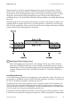


Table Of Contents
- 1 Information on this Manual
- 2 Sunny Island 4548-US/6048-US
- 3 Safety Precautions
- 4 Assembly
- 5 Opening and Closing
- 6 Electrical Connection
- 7 Control Elements
- 8 Initial Start-Up
- 9 Switching On and Off
- 10 Operation
- 11 Archiving Data on an SD Card
- 12 Additional Functions
- 12.1 Load Shedding
- 12.2 Sleep Mode
- 12.3 Time-Controlled Operation
- 12.4 Overload and Short-Circuit Behavior
- 12.5 Mixed Operation with Sunny Island inverters of Different Power
- 12.6 Device Faults and Autostart
- 12.7 Automatic Frequency Synchronization
- 12.8 Time-Controlled Standby
- 12.9 Behavior in the Event of a Failure in a Three-Phase System
- 13 Battery Management
- 14 Connecting External Sources
- 14.1 Generator
- 14.1.1 Parallel Connection
- 14.1.2 Generator Start Options
- 14.1.3 Generator Operation
- 14.1.4 Manual Generator Operation
- 14.1.5 Automatic Generator Operation
- 14.1.6 Limits and Power Control
- 14.1.7 Run Times
- 14.1.8 Operation Together with PV Inverters and Wind Power Inverters
- 14.1.9 Stopping the Generator
- 14.1.10 Stopping the Sunny Island
- 14.1.11 Disturbances
- 14.2 Grid
- 14.2.1 Limits of the Voltage Range and Frequency Range
- 14.2.2 Starting the Sunny Island
- 14.2.3 Operation in the Event of Grid Failure in a Grid-Tie Backup Configuration
- 14.2.4 Backup Operation and Anti-Islanding
- 14.2.5 Grid Reconnection
- 14.2.6 Grid Operation
- 14.2.7 Grid Failure
- 14.2.8 Disturbances
- 14.2.9 Limits and Power Control
- 14.2.10 Operation Together with PV Inverters and Wind Power Inverters
- 14.3 Generator and Grid
- 14.1 Generator
- 15 Relays
- 16 Multicluster Operation
- 16.1 Communication between the Sunny Island inverters
- 16.2 Initial Start-Up of the Multicluster System
- 16.3 Switching a Multicluster System On and Off
- 16.4 Generator Operation
- 16.5 Behavior with Different States of Charge
- 16.6 Testing the Multicluster Communication
- 16.7 Automatic Frequency Synchronization
- 16.8 Updating the Firmware
- 16.9 Error Handling in the Multicluster System
- 16.10 Grid Operation
- 16.11 Generator Emergency Operation
- 17 PV Inverters
- 18 Maintenance and Care
- 19 Parameter Lists
- 20 Troubleshooting
- 21 Accessories
- 22 Technical Data
- 23 Glossary
- 24 Contact

SMA America, LLC 14 Connecting External Sources
Technical description SI4548_6048-US-TB_en-13 125
14.1.6 Limits and Power Control
The voltage limits can be set using the "234.01 GnVtgMin" and "234.02 GnVtgMax" parameters
and the frequency limits for generator operation can be set using the "234.05 GnFrqMin" and
"234.06 GnFrqMax" parameters. If the values are outside these permitted limits, the generator is
disconnected. Slightly narrower limits apply to generator connection.
The voltage and frequency limits are monitored in phases. At least the line conductor on the master
device must comply with the limits defined for connecting the generator. If the limits are not
maintained, slave devices, where applicable, connect or disconnect individually.
The Sunny Island burdens the generator at each line conductor with the current defined in the
parameter "234.03 GnCurNom" as a maximum. The power that is not directly used by the loads
flows into the battery for charging. At the same time, the limits for the AC charging current limit
("210.02 InvChrgCurMax" parameter) on the Sunny Island and the DC charging current limit
("222.01 BatChrgCurMax" parameter) are active.
Low values for this limit may be the reason why the defined generator current cannot be adjusted.
If the battery voltage reaches the charging voltage target value, it is also reduced (absorption phase)
(see Section 13.4 "Charge Control", page 109).
If the "234.15 GnCtlMod" parameter is set to CurFrq, the generator is also limited at frequencies
lower than the nominal frequency ("234.04 GnFrqNom" parameter). This function can be used if the
full generator power is not always available and you want to prevent the generator from being
overloaded. The default setting is only intended to control the nominal generator current.
If the current set using the "234.03 GnCurNom" parameter is not sufficient for powering the loads,
the battery provides support ("real generator support").
The Sunny Island provides all the required reactive power.
System voltage (AC)
The system voltage (AC) depends on the generator voltage when the generator is running.
Generator disconnection by the master
If the master device disconnects the generator, all slave devices are disconnected as well.
Generator disconnection by a slave
If a slave device is disconnected from a generator (and the master continues to be connected
to the generator), the slave device can reconnect once the voltage and frequency are within
the valid range again.
In this case, a monitoring period is running. Only after the time for the "234.12 GnWarmTm"
parameter has expired and after voltage and frequency are determined to be valid does
reconnection take place.
Value for "234.03 GnCurNom" parameter
A sensible value for the "234.03 GnCurNom" parameter is approximately 80% of the
maximum generator current for each line conductor.