
SI4548-US-10 Manual


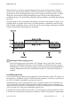


Table Of Contents
- 1 Information on this Manual
- 2 Sunny Island 4548-US/6048-US
- 3 Safety Precautions
- 4 Assembly
- 5 Opening and Closing
- 6 Electrical Connection
- 7 Control Elements
- 8 Initial Start-Up
- 9 Switching On and Off
- 10 Operation
- 11 Archiving Data on an SD Card
- 12 Additional Functions
- 12.1 Load Shedding
- 12.2 Sleep Mode
- 12.3 Time-Controlled Operation
- 12.4 Overload and Short-Circuit Behavior
- 12.5 Mixed Operation with Sunny Island inverters of Different Power
- 12.6 Device Faults and Autostart
- 12.7 Automatic Frequency Synchronization
- 12.8 Time-Controlled Standby
- 12.9 Behavior in the Event of a Failure in a Three-Phase System
- 13 Battery Management
- 14 Connecting External Sources
- 14.1 Generator
- 14.1.1 Parallel Connection
- 14.1.2 Generator Start Options
- 14.1.3 Generator Operation
- 14.1.4 Manual Generator Operation
- 14.1.5 Automatic Generator Operation
- 14.1.6 Limits and Power Control
- 14.1.7 Run Times
- 14.1.8 Operation Together with PV Inverters and Wind Power Inverters
- 14.1.9 Stopping the Generator
- 14.1.10 Stopping the Sunny Island
- 14.1.11 Disturbances
- 14.2 Grid
- 14.2.1 Limits of the Voltage Range and Frequency Range
- 14.2.2 Starting the Sunny Island
- 14.2.3 Operation in the Event of Grid Failure in a Grid-Tie Backup Configuration
- 14.2.4 Backup Operation and Anti-Islanding
- 14.2.5 Grid Reconnection
- 14.2.6 Grid Operation
- 14.2.7 Grid Failure
- 14.2.8 Disturbances
- 14.2.9 Limits and Power Control
- 14.2.10 Operation Together with PV Inverters and Wind Power Inverters
- 14.3 Generator and Grid
- 14.1 Generator
- 15 Relays
- 16 Multicluster Operation
- 16.1 Communication between the Sunny Island inverters
- 16.2 Initial Start-Up of the Multicluster System
- 16.3 Switching a Multicluster System On and Off
- 16.4 Generator Operation
- 16.5 Behavior with Different States of Charge
- 16.6 Testing the Multicluster Communication
- 16.7 Automatic Frequency Synchronization
- 16.8 Updating the Firmware
- 16.9 Error Handling in the Multicluster System
- 16.10 Grid Operation
- 16.11 Generator Emergency Operation
- 17 PV Inverters
- 18 Maintenance and Care
- 19 Parameter Lists
- 20 Troubleshooting
- 21 Accessories
- 22 Technical Data
- 23 Glossary
- 24 Contact

14 Connecting External Sources SMA America, LLC
124 SI4548_6048-US-TB_en-13 Technical description
The following flowcharts provide an overview of the start/stop behavior of the Sunny Island during
automatic generator operation:
Generator Interface "234.07 GnSrtMod" = Manual; Request Via Sunny Island
Generator Interface "234.07 GnSrtMod" = Autostart; Request Via Sunny Island
Multi-phase system
Only the total load power of all line conductors is monitored. Individual phases in a multi-phase
system are not monitored.
The load power is calculated using the Sunny Island power ("111.01 TotInvPwrAt" parameter)
and generator power ("131.01 TotExtPwrAt" parameter).
1 Generator is requested via Sunny Island
2 Manual generator start
3 "Generator is running" detected, beginning of warm up phase
4 Warm-up phase is completed, connection
5 Generator current limit
6 Minimum run time has expired
7 Current is reduced, battery absorption phase
8 Charging process is completed, request signal is disabled
9 Manual generator stop
10 Generator is disconnected
11 Stop time has expired
1 Generator started by Sunny Island
2 Generator Start
3 Beginning of warm up time
4 Warm-up time has expired
5 Generator is connected
6Current limit
7 Minimum running time is expired
8 Current is reduced, battery absorption phase
9 Charging process is completed, generator disconnection
10 Generator power-down time expired, generator disconnection
11 Stop time has expired
Power-dependent generator start
Warm up times, minimum run times and power-down times are also maintained for
power-dependent generator starts.