
SI4548-US-10 Manual


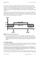


Table Of Contents
- 1 Information on this Manual
- 2 Sunny Island 4548-US/6048-US
- 3 Safety Precautions
- 4 Assembly
- 5 Opening and Closing
- 6 Electrical Connection
- 7 Control Elements
- 8 Initial Start-Up
- 9 Switching On and Off
- 10 Operation
- 11 Archiving Data on an SD Card
- 12 Additional Functions
- 12.1 Load Shedding
- 12.2 Sleep Mode
- 12.3 Time-Controlled Operation
- 12.4 Overload and Short-Circuit Behavior
- 12.5 Mixed Operation with Sunny Island inverters of Different Power
- 12.6 Device Faults and Autostart
- 12.7 Automatic Frequency Synchronization
- 12.8 Time-Controlled Standby
- 12.9 Behavior in the Event of a Failure in a Three-Phase System
- 13 Battery Management
- 14 Connecting External Sources
- 14.1 Generator
- 14.1.1 Parallel Connection
- 14.1.2 Generator Start Options
- 14.1.3 Generator Operation
- 14.1.4 Manual Generator Operation
- 14.1.5 Automatic Generator Operation
- 14.1.6 Limits and Power Control
- 14.1.7 Run Times
- 14.1.8 Operation Together with PV Inverters and Wind Power Inverters
- 14.1.9 Stopping the Generator
- 14.1.10 Stopping the Sunny Island
- 14.1.11 Disturbances
- 14.2 Grid
- 14.2.1 Limits of the Voltage Range and Frequency Range
- 14.2.2 Starting the Sunny Island
- 14.2.3 Operation in the Event of Grid Failure in a Grid-Tie Backup Configuration
- 14.2.4 Backup Operation and Anti-Islanding
- 14.2.5 Grid Reconnection
- 14.2.6 Grid Operation
- 14.2.7 Grid Failure
- 14.2.8 Disturbances
- 14.2.9 Limits and Power Control
- 14.2.10 Operation Together with PV Inverters and Wind Power Inverters
- 14.3 Generator and Grid
- 14.1 Generator
- 15 Relays
- 16 Multicluster Operation
- 16.1 Communication between the Sunny Island inverters
- 16.2 Initial Start-Up of the Multicluster System
- 16.3 Switching a Multicluster System On and Off
- 16.4 Generator Operation
- 16.5 Behavior with Different States of Charge
- 16.6 Testing the Multicluster Communication
- 16.7 Automatic Frequency Synchronization
- 16.8 Updating the Firmware
- 16.9 Error Handling in the Multicluster System
- 16.10 Grid Operation
- 16.11 Generator Emergency Operation
- 17 PV Inverters
- 18 Maintenance and Care
- 19 Parameter Lists
- 20 Troubleshooting
- 21 Accessories
- 22 Technical Data
- 23 Glossary
- 24 Contact

SMA America, LLC 14 Connecting External Sources
Technical description SI4548_6048-US-TB_en-13 123
The time intervals t1 and t2 are assigned charge states for start-up and stop with the "235.03
GnSocTm1Str", "235.04 GnSocTm1Stp", "235.05 GnSocTm2Str" and "235.06 GnSocTm2Stp"
parameters. GnSocTm1Str designates the battery state of charge at which the generator is started
during the t1 time and GnSocTm1Stp designates the state of charge at which the generator is
switched off during t1. The GnSocTm2Str and GnSocTm2Stp parameters are similarly defined during
the time t2.
The following figure shows an example of the settings if operation of the generator at night is to be
avoided as much as possible. From 6 am to 10 pm the generator is activated at a state of charge
(SOC) of 40%, at night (from 10 pm to 6 am), however, the state of charge of the battery is allowed
to drop to 30% before the diesel generator is activated.
Load-Dependent Start
In case increased energy demands arise, the generator can be requested for support. This function can
be switched on or off (default) using the "235.09 GnPwrEna" parameter. The function is only effective if
the "235.01 GnAutoEna" parameter is simultaneously set to On.
The load limit for the request and the generator stop is configured using the "235.10 GnPwrStr" and
"235.11 GnPwrStp" parameters. The average time by which an average value for the load power is
calculated can be set using "235.12 GnPwrAvgTm". This prevents temporary power consumption peaks
of a few seconds from causing a power-dependent generator start.
If the generator has been started due to the load, it runs according to the minimum generator run time.
If, once this time has expired, the average power is below the cutoff limit, the generator is stopped again.
Reaching the float charging process
If the float charging process (see Section 13.4 "Charge Control", page 109) is activated
before the cutoff limit (GnSocTm1Stp or GnSocTm2Stp) is reached, the generator request is
disabled again. If a full or equalization charge is active, the generator is only stopped after this
charge is completed and not when "235.04 GnSocTm1Stp" or "235.06 GnSocTm2Stp" is
reached.