
SI4548-US-10 Manual

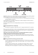


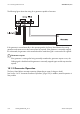
Table Of Contents
- 1 Information on this Manual
- 2 Sunny Island 4548-US/6048-US
- 3 Safety Precautions
- 4 Assembly
- 5 Opening and Closing
- 6 Electrical Connection
- 7 Control Elements
- 8 Initial Start-Up
- 9 Switching On and Off
- 10 Operation
- 11 Archiving Data on an SD Card
- 12 Additional Functions
- 12.1 Load Shedding
- 12.2 Sleep Mode
- 12.3 Time-Controlled Operation
- 12.4 Overload and Short-Circuit Behavior
- 12.5 Mixed Operation with Sunny Island inverters of Different Power
- 12.6 Device Faults and Autostart
- 12.7 Automatic Frequency Synchronization
- 12.8 Time-Controlled Standby
- 12.9 Behavior in the Event of a Failure in a Three-Phase System
- 13 Battery Management
- 14 Connecting External Sources
- 14.1 Generator
- 14.1.1 Parallel Connection
- 14.1.2 Generator Start Options
- 14.1.3 Generator Operation
- 14.1.4 Manual Generator Operation
- 14.1.5 Automatic Generator Operation
- 14.1.6 Limits and Power Control
- 14.1.7 Run Times
- 14.1.8 Operation Together with PV Inverters and Wind Power Inverters
- 14.1.9 Stopping the Generator
- 14.1.10 Stopping the Sunny Island
- 14.1.11 Disturbances
- 14.2 Grid
- 14.2.1 Limits of the Voltage Range and Frequency Range
- 14.2.2 Starting the Sunny Island
- 14.2.3 Operation in the Event of Grid Failure in a Grid-Tie Backup Configuration
- 14.2.4 Backup Operation and Anti-Islanding
- 14.2.5 Grid Reconnection
- 14.2.6 Grid Operation
- 14.2.7 Grid Failure
- 14.2.8 Disturbances
- 14.2.9 Limits and Power Control
- 14.2.10 Operation Together with PV Inverters and Wind Power Inverters
- 14.3 Generator and Grid
- 14.1 Generator
- 15 Relays
- 16 Multicluster Operation
- 16.1 Communication between the Sunny Island inverters
- 16.2 Initial Start-Up of the Multicluster System
- 16.3 Switching a Multicluster System On and Off
- 16.4 Generator Operation
- 16.5 Behavior with Different States of Charge
- 16.6 Testing the Multicluster Communication
- 16.7 Automatic Frequency Synchronization
- 16.8 Updating the Firmware
- 16.9 Error Handling in the Multicluster System
- 16.10 Grid Operation
- 16.11 Generator Emergency Operation
- 17 PV Inverters
- 18 Maintenance and Care
- 19 Parameter Lists
- 20 Troubleshooting
- 21 Accessories
- 22 Technical Data
- 23 Glossary
- 24 Contact

SMA America, LLC 14 Connecting External Sources
Technical description SI4548_6048-US-TB_en-13 119
Autostart
This allows autostart generators to be directly integrated. They have a separate internal controller that
controls the start procedure.
The Sunny Island requests the generator via the GnReq signal. If the generator voltage and frequency
are within the set limits (see Section 14.1.6 "Limits and Power Control", page 125), the device is
synchronized and connected following the warm up time.
The Sunny Island keeps the request signal active until a disconnection is made and the set
power-down time has expired.
GenReq signal
The GnReq signal (see Section 15 "Relays", page 140) is set for signaling the generator
request and can thus be used as an alarm contact (in this case: a bulb). If no request is pending,
the signal is reset.
If an internal request is sent while the generator is already running, the signal is disabled until
the generator is externally stopped and the stop time has expired (30 seconds).
Disconnecting the generator
A disconnect should be positioned between the Sunny Island and the generator. If the
generator is to be stopped, it is first manually disconnected using the disconnect and then it is
stopped. This prevents actuation of the generator by the Sunny Island.
Shut-off delay
Autostart generators can have an internal shut-off delay that is only activated when the request
has been disabled. This can extend the power-down time accordingly.
Internal warm-up phase
With some generator types, the voltage is only switched to the output after the internal warm-up
phase is finished. Therefore, the time of the generator activation sequence is monitored
internally:
• 2 x "234.12 GnWarmTm" + 2 minutes for manual and automatic start