
SI4548-US-10 Manual
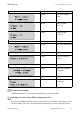
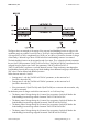
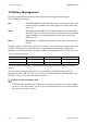
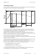
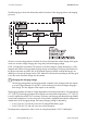
Table Of Contents
- 1 Information on this Manual
- 2 Sunny Island 4548-US/6048-US
- 3 Safety Precautions
- 4 Assembly
- 5 Opening and Closing
- 6 Electrical Connection
- 7 Control Elements
- 8 Initial Start-Up
- 9 Switching On and Off
- 10 Operation
- 11 Archiving Data on an SD Card
- 12 Additional Functions
- 12.1 Load Shedding
- 12.2 Sleep Mode
- 12.3 Time-Controlled Operation
- 12.4 Overload and Short-Circuit Behavior
- 12.5 Mixed Operation with Sunny Island inverters of Different Power
- 12.6 Device Faults and Autostart
- 12.7 Automatic Frequency Synchronization
- 12.8 Time-Controlled Standby
- 12.9 Behavior in the Event of a Failure in a Three-Phase System
- 13 Battery Management
- 14 Connecting External Sources
- 14.1 Generator
- 14.1.1 Parallel Connection
- 14.1.2 Generator Start Options
- 14.1.3 Generator Operation
- 14.1.4 Manual Generator Operation
- 14.1.5 Automatic Generator Operation
- 14.1.6 Limits and Power Control
- 14.1.7 Run Times
- 14.1.8 Operation Together with PV Inverters and Wind Power Inverters
- 14.1.9 Stopping the Generator
- 14.1.10 Stopping the Sunny Island
- 14.1.11 Disturbances
- 14.2 Grid
- 14.2.1 Limits of the Voltage Range and Frequency Range
- 14.2.2 Starting the Sunny Island
- 14.2.3 Operation in the Event of Grid Failure in a Grid-Tie Backup Configuration
- 14.2.4 Backup Operation and Anti-Islanding
- 14.2.5 Grid Reconnection
- 14.2.6 Grid Operation
- 14.2.7 Grid Failure
- 14.2.8 Disturbances
- 14.2.9 Limits and Power Control
- 14.2.10 Operation Together with PV Inverters and Wind Power Inverters
- 14.3 Generator and Grid
- 14.1 Generator
- 15 Relays
- 16 Multicluster Operation
- 16.1 Communication between the Sunny Island inverters
- 16.2 Initial Start-Up of the Multicluster System
- 16.3 Switching a Multicluster System On and Off
- 16.4 Generator Operation
- 16.5 Behavior with Different States of Charge
- 16.6 Testing the Multicluster Communication
- 16.7 Automatic Frequency Synchronization
- 16.8 Updating the Firmware
- 16.9 Error Handling in the Multicluster System
- 16.10 Grid Operation
- 16.11 Generator Emergency Operation
- 17 PV Inverters
- 18 Maintenance and Care
- 19 Parameter Lists
- 20 Troubleshooting
- 21 Accessories
- 22 Technical Data
- 23 Glossary
- 24 Contact

13 Battery Management SMA America, LLC
110 SI4548_6048-US-TB_en-13 Technical description
The following figure shows the relationship and the flowchart of the charging phases and charging
processes.
Once this constant voltage phase is finished, the Sunny Island switches to float charge which again
carries out constant voltage charging but at a greatly reduced charging voltage
("222.10 ChrgVtgFlo" parameter). The purpose of the float charge is to keep the battery in a fully
charged state without causing premature aging through overcharging. The Sunny Island remains in
this phase until either more than 30% of the nominal capacity has been used (all discharges are
added up) or the state of charge is below 70%. When the Sunny Island is operating on the utility grid,
it can also switch from float charge into silent mode.
The charging capability of batteries is highly dependent on the battery temperature. For temperatures
<77°F (25°C), the charging voltage must be slightly increased, and for temperatures > 77°F (25°C)
it must be slightly decreased. This is necessary to prevent overcharging and deep discharge reliably
at any battery temperature. For this reason, the Sunny Island is equipped with automatic temperature
compensation of the charging voltage. The battery charging voltage is adjusted by:
• 2 mV/°F (4 mV/°C) and cell, in the case of VLA and FRLA battery types
• 0 mV/°F (0 mV/°C), and cell, in the case of NiCd batteries
The temperature compensation value can be set using the parameter "222.11 BatTmpCps".
Changing the charging voltage
The charging voltage does not change erratically. Instead, it slowly changes to the new setpoint
at a rate of approximately 0.5 mV/cell*s when switching from constant voltage charging to
float charge. This also happens if the setpoint is set manually.