
SI4548-US-10 Manual
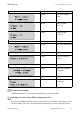
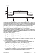
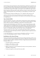
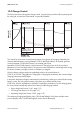
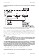
Table Of Contents
- 1 Information on this Manual
- 2 Sunny Island 4548-US/6048-US
- 3 Safety Precautions
- 4 Assembly
- 5 Opening and Closing
- 6 Electrical Connection
- 7 Control Elements
- 8 Initial Start-Up
- 9 Switching On and Off
- 10 Operation
- 11 Archiving Data on an SD Card
- 12 Additional Functions
- 12.1 Load Shedding
- 12.2 Sleep Mode
- 12.3 Time-Controlled Operation
- 12.4 Overload and Short-Circuit Behavior
- 12.5 Mixed Operation with Sunny Island inverters of Different Power
- 12.6 Device Faults and Autostart
- 12.7 Automatic Frequency Synchronization
- 12.8 Time-Controlled Standby
- 12.9 Behavior in the Event of a Failure in a Three-Phase System
- 13 Battery Management
- 14 Connecting External Sources
- 14.1 Generator
- 14.1.1 Parallel Connection
- 14.1.2 Generator Start Options
- 14.1.3 Generator Operation
- 14.1.4 Manual Generator Operation
- 14.1.5 Automatic Generator Operation
- 14.1.6 Limits and Power Control
- 14.1.7 Run Times
- 14.1.8 Operation Together with PV Inverters and Wind Power Inverters
- 14.1.9 Stopping the Generator
- 14.1.10 Stopping the Sunny Island
- 14.1.11 Disturbances
- 14.2 Grid
- 14.2.1 Limits of the Voltage Range and Frequency Range
- 14.2.2 Starting the Sunny Island
- 14.2.3 Operation in the Event of Grid Failure in a Grid-Tie Backup Configuration
- 14.2.4 Backup Operation and Anti-Islanding
- 14.2.5 Grid Reconnection
- 14.2.6 Grid Operation
- 14.2.7 Grid Failure
- 14.2.8 Disturbances
- 14.2.9 Limits and Power Control
- 14.2.10 Operation Together with PV Inverters and Wind Power Inverters
- 14.3 Generator and Grid
- 14.1 Generator
- 15 Relays
- 16 Multicluster Operation
- 16.1 Communication between the Sunny Island inverters
- 16.2 Initial Start-Up of the Multicluster System
- 16.3 Switching a Multicluster System On and Off
- 16.4 Generator Operation
- 16.5 Behavior with Different States of Charge
- 16.6 Testing the Multicluster Communication
- 16.7 Automatic Frequency Synchronization
- 16.8 Updating the Firmware
- 16.9 Error Handling in the Multicluster System
- 16.10 Grid Operation
- 16.11 Generator Emergency Operation
- 17 PV Inverters
- 18 Maintenance and Care
- 19 Parameter Lists
- 20 Troubleshooting
- 21 Accessories
- 22 Technical Data
- 23 Glossary
- 24 Contact

SMA America, LLC 13 Battery Management
Technical description SI4548_6048-US-TB_en-13 109
13.4 Charge Control
The Sunny Island uses a three-phase charge control, using the IUoU procedure. When operating with
the utility grid, a fourth level, Silent Mode, is optionally available.
The I stands for the constant current phase (I phase). In this phase, the charging is limited by the
maximum defined battery current (parameter "222.01 BatChrgCurMax"), the nominal generator
current (parameter "234.03 GnCurNom"), the nominal grid current
(parameter "232.03 GdCurNom") or the maximum AC charging current of the Sunny Island
(parameter "210.02 InvChrgCurMax"). The respective value reached first is the limiting value. During
this phase, the battery voltage increases as the battery is charged.
Once the battery voltage reaches the predefined value for the second phase Uo
("222.07 to 222.09", ChrgVtgBoost or ChrgVtgFul or ChrgVtgEqu parameters), the constant voltage
charging (absorption phase) begins.
In this phase, the battery voltage is maintained at a constant level, resulting in a continually decreasing
battery current. The Sunny Island remains in this phase for a defined period of time
("222.02 to 222.04", AptTmBoost or AptTmFul or AptTmEqu" parameters). For this charging phase,
the Sunny Island automatically selects one of three possible charging methods:
• Boost charge (see Section 13.4.1, page 111)
• Full charge (see Section 13.4.2, page 111)
• Equalizing charge (see Section 13.4.3, page 112)
The remaining charging time (display value "120.04 AptTmRmg") of this phase and the actual
process (display value "120.05 BatChrgOp") can be read on the display.