
SI4548-US-10 Manual
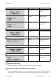
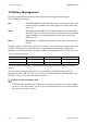
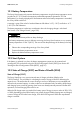
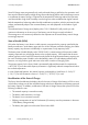
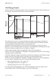
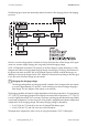
Table Of Contents
- 1 Information on this Manual
- 2 Sunny Island 4548-US/6048-US
- 3 Safety Precautions
- 4 Assembly
- 5 Opening and Closing
- 6 Electrical Connection
- 7 Control Elements
- 8 Initial Start-Up
- 9 Switching On and Off
- 10 Operation
- 11 Archiving Data on an SD Card
- 12 Additional Functions
- 12.1 Load Shedding
- 12.2 Sleep Mode
- 12.3 Time-Controlled Operation
- 12.4 Overload and Short-Circuit Behavior
- 12.5 Mixed Operation with Sunny Island inverters of Different Power
- 12.6 Device Faults and Autostart
- 12.7 Automatic Frequency Synchronization
- 12.8 Time-Controlled Standby
- 12.9 Behavior in the Event of a Failure in a Three-Phase System
- 13 Battery Management
- 14 Connecting External Sources
- 14.1 Generator
- 14.1.1 Parallel Connection
- 14.1.2 Generator Start Options
- 14.1.3 Generator Operation
- 14.1.4 Manual Generator Operation
- 14.1.5 Automatic Generator Operation
- 14.1.6 Limits and Power Control
- 14.1.7 Run Times
- 14.1.8 Operation Together with PV Inverters and Wind Power Inverters
- 14.1.9 Stopping the Generator
- 14.1.10 Stopping the Sunny Island
- 14.1.11 Disturbances
- 14.2 Grid
- 14.2.1 Limits of the Voltage Range and Frequency Range
- 14.2.2 Starting the Sunny Island
- 14.2.3 Operation in the Event of Grid Failure in a Grid-Tie Backup Configuration
- 14.2.4 Backup Operation and Anti-Islanding
- 14.2.5 Grid Reconnection
- 14.2.6 Grid Operation
- 14.2.7 Grid Failure
- 14.2.8 Disturbances
- 14.2.9 Limits and Power Control
- 14.2.10 Operation Together with PV Inverters and Wind Power Inverters
- 14.3 Generator and Grid
- 14.1 Generator
- 15 Relays
- 16 Multicluster Operation
- 16.1 Communication between the Sunny Island inverters
- 16.2 Initial Start-Up of the Multicluster System
- 16.3 Switching a Multicluster System On and Off
- 16.4 Generator Operation
- 16.5 Behavior with Different States of Charge
- 16.6 Testing the Multicluster Communication
- 16.7 Automatic Frequency Synchronization
- 16.8 Updating the Firmware
- 16.9 Error Handling in the Multicluster System
- 16.10 Grid Operation
- 16.11 Generator Emergency Operation
- 17 PV Inverters
- 18 Maintenance and Care
- 19 Parameter Lists
- 20 Troubleshooting
- 21 Accessories
- 22 Technical Data
- 23 Glossary
- 24 Contact

13 Battery Management SMA America, LLC
106 SI4548_6048-US-TB_en-13 Technical description
13 Battery Management
The battery management of the Sunny Island supports the following three battery types
("221.01 BatTyp" parameter):
The battery capacity ("221.02 BatCpyNom" parameter) is to be entered as the nominal capacity for
a 20 hour discharge (C20). If this information is not available from the battery manufacturer's
datasheet, it can be calculated from the data for different discharge times (120 h, 100 h, 20 h, 5 h,
1 h) in the following manner:
100 Ah (C20) per 1 kW of the PV plant output power should be present as a minimum battery
capacity.
The Sunny Island is designed and preset for a nominal battery voltage (parameter "221.03
BatVtgNom") of 48 V (24 cells for every 2 V) with lead-acid batteries (FLA and VRLA) and 45.6 V
(38 cells for every 1.2 V) with nickel cadmium batteries.
FLA Flooded Lead Acid: Closed lead-acid batteries with liquid electrolyte in all
standard designs available on the market (grid plate, tubular plate, small,
large, etc.).
VRLA Valve Regulated Lead Acid: Closed lead-acid batteries with immobilized
electrolyte in gel or AGM (Absorbent Glass Mat Separator) in all standard
designs available on the market (grid plate, tubular plate, small, large,
AGM, Gel, etc.)
NiCd Nickel Cadmium: Sealed pocket-type plate or fiber plate nickel-cadmium
batteries.
C20 C120/1.18 C20 C10/0.92
C20 C100/1.15 C20 C5/0.81
C20 C20 C20 C1/0.57
Failure of individual battery cells
If individual battery cells fail over several years of continuous operation, the nominal voltage
can be set in the range from 42 V to 48 V. Up to three individual cells can be removed and the
plant can still continue to operate.