
Manual
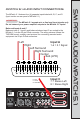

Mpatch 5.1 Audio input Connections
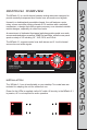
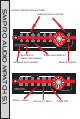
The MPatch 5.1 features four (4) separate inputs labeled A, B, C, and D
(Input section on rear panel of MPatch 5.1).
The MPatch 5.1 accepts mic or line level input signals only.
Do not connect your power amplifier outputs to the MPatch 5.1 inputs!
Balanced Inputs A and C
Balanced main 5.1 input A and balanced stereo input C are routed to the
MPatch 5.1 via the 25-pin DSub connector. The wiring scheme follows the
TASCAM format, a widely-used protocol for connecting assorted audio
equipment via 25-pin D-Sub connectors.
SM PRO AUDIO MPatch 5.1
important
Power Input
OFF ON
POWER
L
R
LS
RS
LFE
C
L
R
Balan ce d
Left Right
LRL SR SCLFE
INPUT BINP UT D
Stereo Sp eaker Outs
Surroun d Speaker Ou tputs
INPUT A+ C
SLAVE OUTPUT
Balance d input and Li nk to output
(90-240 V ac)
8 7 6 5 4 3 2 1910111213
141516171819202122232425
G C H G C H G C H G C H G C H G C H G C H G C H
1 2 3 4 5 6 7 8
H = HOT
C = COLD
G = GROUND
Pin-out for TASCAM DB25 8 Channel Balanced Connector
Left
Right
Left Surround
Right Surround
Center
Sub (LFE)
Input A
1-6 = 5.1 Signal
Input C
7 = Stereo Left
8 = Stereo Right
SM PRO AUDIO MPatch 5.1
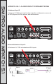
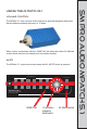
Mpatch 5.1 Audio input Connections
Unbalanced Input B
Unbalanced 5.1 RCA inputs, ideal for direct output from unbalanced sources such
as DVD players, Blue Ray players, and media servers.
Balanced/Unbalanced Input D
L/R balanced 1/4” TRS and unbalanced RCA inputs
Power Input
OFF ON
POWER
L
R
LS
RS
LFE
C
L
R
Balan ce d
Left Right
LRL SR SCLFE
INPUT BINP UT D
Stereo Sp eaker Outs
Surroun d Speaker Ou tputs
INPUT A+C
SLAVE OUTPUT
Balance d input and Li nk to output
(90-240 V ac)
Power Input
OFF ON
POWER
L
R
LS
RS
LFE
C
L
R
Balan ce d
Left Right
LRL SR SCLFE
INPUT BINP UT D
Stereo Sp eaker Outs
Surroun d Speaker Ou tputs
INPUT A+C
SLAVE OUTPUT
Balance d input and Li nk to output
(90-240 V ac)
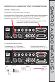
Tip
Ring
Sleeve