M-Patch 2 Operating Manual August 2012
SAFETY INSTRUCTIONS CAUTION: To reduce the risk of electrical shock, do not remove the cover or rear panel of this unit. No user serviceable parts inside. Please refer servicing to qualified personnel only. WARNING: To reduce the risk of fire or electrical shock do not expose this appliance to rain or moisture. DETAILED SAFETY INSTRUCTIONS: All safety and operation instructions of this manual should be read and adhered to before operation.
FOREWORD Dear Customer, Thank you very much for expressing your confidence in SM ProAudio products by purchasing this unit. The M-Patch 2 has been designed to be used as a standard tool for home/pro studios, P.A. rental companies, Schools and in many other situations where audio products would be used. With much experience in the audio industry over a long period of time, and along with valuable suggestions from our customers, our engineers have developed a product we know you will be satisfied with.
M-Patch 2 Main Features Professional, multi-purpose passive volume attenuator with built in headphone amplifier. • • • • • • • • • • • High quality ‚passive volume‘ attenuator Great monitor switching device 2 x Input channels, 2 x Output channels Combo, RCA, & 3.
3. Installation Your SM Pro Audio M-Patch 2 was carefully packed in the factory and the packaging was designed to protect the unit from rough handling. Nevertheless, we recommend that you carefully examine the packaging and its contents for any signs of physical damage, which may have occurred in transit. If the unit is damaged, please do not return it to us, but notify your dealer and the shipping company immediately, otherwise claims for damage or replacement may not be granted.
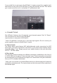
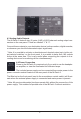
If you would like to rack-mount the M-Patch 2, simply connect the supplied rack/ stand ears to each side of the M-Patch 2 using the included screws. This allows you to rack-mount the unit in a standard 19” professional rack. 4. Connections The M-Patch 2 features two (2) separate input channels named “Aux” & “Stereo”. The connections are found on the rear panel. (Input section on rear panel of M-Patch 2). * Note: The M-Patch 2 accepts mic or line level input signals.
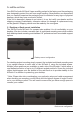
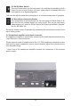
4.3 Analog Audio Outputs The M-Patch 2 features two (2) pairs (L&R) of XLR balanced analog output connectors on the rear panel. These are labeled “1” & “2”. Connect these outputs to your destination device (active monitors, digital recorder, or wherever you need the attenuated output signal sent). * Note: It is possible to activate or deactivate each desired output pair via the ‚output selector switches‘ on the front panel. It is possible to have both 1&2 outputs active at the same time.
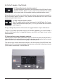
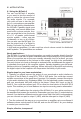
5. FRONT PANEL CONTROLS 5.1 Stereo/Aux input selection control The input selection controls on the front panel of the M-Patch 2 allow selection of either ‚Stereo‘ or ‚Aux‘ input source material to be routed to the output pairs for immediate listening and attenuation control. Select the “stereo” position to activate the main stereo input source connected to the XLR/combo inputs, or select “Aux” position to activate the RCA and 3.5mm stereo mini-jack input source. 5.
5.4 On/Off Mute Switch The on/off mute switch on the front panel is for enabling and disabling the MPatch 2‘s built in mute function. All audio signal output is disabled when the mute switch is in a depressed position. The mute led will illuminate when the system is in a current muted state of operation. 5.5 Mono/Stereo Summing Switch The mono/stereo summing switch on the front panel of the M-Patch 2 allows you to sum a stereo signal to a mono signal.
6. APPLICATION 6.1 Using the M-Patch 2 You can use M-Patch 2 anywhere you want to trim the amount of gain; ie, reduce the volume of analog audio signals. For example, you could use one to trim the output of a microphone pre-amplifier. With its high-quality potentiometer, the M-Patch 2 passes signal more accurately, and sounds better than most built-in volume controls. Another use might be to trim the levels of a 5.
7. SPECIFICATIONS AUDIO INPUTS Connectors AUDIO OUTPUTS Output Connectors HEADPHONE OUTPUT Output Connectors Frequency response Maximum output level POWER External PHYSICAL Dimensions Net weight • 2 x XLR Combo connectors • 1 x stereo RCA pair (L&R) • 1 x stereo 3.5mm jack • 2 x XLR output pairs (A-/L&R, B-/L&R) • 1 x 14” TRS stereo output • 20Hz - 20Hz +/- 0.5dB • 320mW into 32Ω • DC12-16V adaptor • 22cm x 12cm x 8.6 cm • approx. 1 kg 8. Warranty 8.
8.4 Warranty Regulations 8.4.1. Warranty services will be furnished only if the product is accompanied by an original retail dealer‘s invoice. Any product deemed eligible for repair or replacement by SM Pro Audio under the terms of this warranty will be repaired or replaced in the best possible manner. 8.4.2.