Operating Manual – SM EP84 Manual Version 1.
SAFETY INSTRUCTIONS CAUTION: To reduce the risk of electrical shock, do not remove the cover or rear panel of this unit. Do not expose this appliance to rain or moisture. No user serviceable parts inside. Please refer servicing to qualified personnel only. Retain Instructions: Please retain all safety and operating instructions for future reference. Ventilation: Do not impede the flow of air through the ventilation openings.
EP84 Main Features The EP84 is a professional multi-channel microphone preamplifier featuring: - 8 x discrete microphone preamplifiers Modular PCB design Ultra-wide dynamic range Low-noise operating Levels + 48V Phantom power per channel -20dB PAD per channel Phase reverse per channel Gain control per channel Peak LED indicator per channel 80 Hz low-cut (high-pass) filter per channel Optional ADAT interface available (PR8IIA) FOREWORD Dear Customer, Firstly, we would like to thank you for purchasing our E
TABLE OF CONTENTS SAFETY INSTRUCTIONS 2 EP84 Main Features and Foreword 3 1. INTRODUCTION 5 2. 2.1 2.2 THE DESIGN 5 High quality components and design Inputs and outputs 3. 3.1 3.2 3.
1. INTRODUCTION In purchasing the new EP84, you have acquired a multi-channel microphone/instrument preamplifier of high class that meets the demands of the home and professional studio. A modular designed unit, the EP84 features eight individual channels of professional quality microphone pre-amplification in a solid 2RU rack-mountable format. Each channel features its own level control, 20dB pad, phantom power, low-cut (high-pass) filter, phase reverse, and LED peak level indicator.
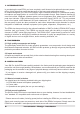
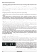
EP84 front panel * Note: Please take into consideration ventilation of your equipment. A well-ventilated equipment rack will ensure optimum operation and longevity of your equipment. It’s often a good idea to leave 1 free rack-bay position between your equipment to allow ventilation As to avoid overheating, please do not place the EP84 on high temperature devices such as power amplifiers. 3.
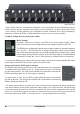
3.4 Audio Connections EP84 rear panel Analog Inputs 8 x combo (XLR & TS) input connectors can be found on the front panel. These are the direct analog inputs to the EP84’s 8 individual preamplifier modules. Input your audio source material via either XLR or 1/4” TS cable connectors. Analog outputs Both balanced +4dB XLR and unbalanced -10dB 1/4” TS analog output connectors are provided for each of the eight (8) preamplifier channels.
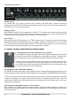
* Phantom power is a voltage distribution system utilizing standard microphone cable. It is useful (and often required) for powering condenser microphones connected to your audio system. If any of your microphones require phantom power, simply enable the corresponding channels phantom power switch to activate a constant 48v power supply. 4.
Make the necessary connections - Connect your desired source signals to the EP84 via the front panel COMBO connectors (either XLR or 1/4” jack connector). - If you would like to insert an external processor (ie. Compressor, EQ, etc) in the channels audio signal path, connect the outboard device using a standard 1/4” TRS insert cable. - Make the necessary connections from the corresponding channel outputs on the rear of the EP84 to your desired destination inputs (Mixer, recorder, etc).
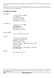
* Note: Both analog outputs from the EP84 and the PR8IIA’s ADAT digital output function simultaneously. Enhance the front end of any ADAT compatible multi-track digital recording system with the PR8IIA. Ask your dealer for more information. 6. SPECIFICATIONS MIC INPUTS Connector: XLR on COMBO Type: Balanced Impedance: 47K Ohms Min sensitivity: -60 dB Peak input level: +9.
7. WARRANTY 7.1 WARRANTY CARD AND/OR WEBSITE REGISTRATION To be protected by this warranty the purchaser of the product must complete an SM Pro Audio product registration procedure. Product registration is available via two methods: - Complete and return the enclosed warranty card within 14 days of the date of purchase to SM Pro Audio (see address below). - Complete an online product registration form at the SM Pro Audio website. www.smproaudio.com 7.
7.4 WARRANTY REGULATIONS - Warranty can only be serviced when accompanying proof of purchase is provided. Dealers invoice and date stamp required. - SM Pro Audio will endeavor to repair or replace any product under the terms of this warranty within 30 days of receipt of the product at SM Pro Audio.