
Install Instructions


31
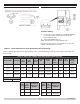
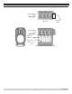
Figure 27 - Riello Electrode Setting
Figure 28 -Riello Turbulator Setting
17 - OIL BURNER, NOZZLE, & AIR SETTINGS
Turbulator Setting
A. Loosen nut (1) turn SCREW (2) until INDEX MARKER
(3) is aligned with correct index number as per
Burner Settings Table.
B. Tighten RETAINING NUT (1).
NOTE: Zero and four are scale indicators only.
From left to right, rst line is 4 and last line 0. On some
models, scale indicators are 0 and 3.
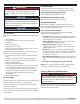
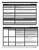
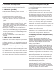
Table 11 - Riello 40F Chimney Vent Preliminary Burner Settings
Burner settings provided are for initial startup only. Final adjustments must be made using combustion test
instruments.
TABLE 11: RIELLO 40F CHIMNEY VENT PRELIMINARY BURNER SETTINGS
Boiler Model Head Type
Inser-
tion
Depth
Firing
Rate
[GPH]
Com-
bustion
Liner
Nozzle
Mfr.
Nozzle
Type
Pump
Pres-
sure
[PSI]
Head
Setting
Air
Setting
Rated
AFUE
Efciency
[%]
Q3-4
Reverse 2.75" 0.75
Oval Delavan
0.65x60W 150 1 3.6 87.0
Q3-5
Standard 2.75" 1.00
None Delavan
0.75x60B 175 1 2.4 87.0
Q3-6
Standard 2.75" 1.30
V6 Delavan
1.00x45B 175 2 3.6 87.0
Q3-7
Standard 2.75" 1.65
V7 Delavan
1.35x60B 150 4 8.0 87.0
Timings
Pre-purge 12 seconds
Boiler
Model
Riello
Oil
Burner
Model
Slant Fin Oil
Burner Part
Number
Q3-4 40F3
473014000
Q3-5 40F5
473015000
Boiler
Model
Riello
Oil
Burner
Model
Slant Fin Oil
Burner Part
Number
Q3-6 40F5
473016000
Q3-7 40F5
473017000
PN 473900000