
Install Instructions

30
16 - OPERATING THE BOILER - SYSTEM START-UP
4. Final Burner Adjustments
: Final burner
adjustments must be made using combustion test
instruments.
A. Check breech draft to verify between 0.00” WC and
-0.05” WC, or otherwise adjust draft to -0.05” WC (or
less than zero.)
B. After operating 10 minutes to warm up boiler, use
combustion test equipment to take smoke reading in
ue pipe between boiler and draft regulator. Smoke
reading should be zero to trace (Shell Bacharach
Scale).
C. New boiler may require more than 10 minutes to burn
clean due to oil lm on new heat exchanger. If smoke
reading is zero, gradually close burner’s air adjustment
to obtain smoke reading showing trace smoke reading.
Once smoke reading is trace, measure CO
2
and as
insurance margin increase air to sufciently reduce
CO
2
by 1/2% to 1%.
D. If clean re cannot be obtained, it is necessary to
verify burner head alignment. If re continues to be
smoky, replace nozzle.
CAUTION
Do not run boiler unattended until following procedure
is completed. Failure to follow these instructions could
result in minor or moderate injury.
!
E. Once burner is completely adjusted, start and stop
burner several times to assure good operation with no
uttering or rumbling. Verify there are no oil leaks,
record nozzle size, oil pressure, combustion readings,
and air settings on tag or label attached to burner or,
boiler.
16.10 Check High Temperature Limit Control.
Jumper thermostat terminals. Allow burner to operate until
shut down by limit. Installation is not considered complete
until this check has been made.
16.11 Test Low Water Cut-Off Operation. See
Figure 26, Page 28 and 29.
16.12 If Controls Do Not Meet Requirements
replace control and repeat checkout procedures.
16.13 Nozzles And Electrodes
: Use proper size,
spray angle, and spray pattern nozzle.
A. Refer to “17 - Oil Burner, Nozzle, & Air Settings” on
page 31.
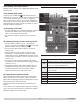
B. To install nozzle, remove nozzle line electrode
assembly, if necessary remove retention ring
assembly, install and tighten nozzle. Be careful not to
damage electrode insulators or bend electrode tips.
C. After installing nozzle, reassemble nozzle line
electrode assembly and set electrode tip spacing.
D. Electrode tip spacing may need to be set prior to
reassembling nozzle line electrode assembly. Refer
to gures on following pages for setting electrode tip
spacing on Beckett.
16.14 Check Thermostat Operation:
Thermostat
location has important effect on operation of boiler system.
A. Follow instructions included with your thermostat.
Typically, thermostat is located about ve feet above
oor on inside wall.
B. Thermostat should be located to sense average room
temperature.
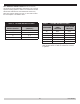
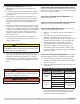
Table 10 - Thermostat locations to Avoid
DEAD
SPOTS
HOT SPOTS COLD SPOTS
Behind
doors
Concealed pipes
Concealed pipes
or ducts
Fireplace
TV sets Stairwell drafts
Corners &
alcoves
Radios Door drafts
Lamps
Unheated room
on other side of
wall
Direct sunlight
Kitchens
C. Verify room temperature reaches selected
temperature setting, thermostat should turn boiler’s
burner off, and once room temperature falls few
degrees boiler starts operating again.
WARNING
Remove jumper after following check.
!
WARNING
Electrical shock hazard. Following safety checks shall
be completed by qualied agency. Failure to do so
could result in death or serious injury.
!
PN 473900000