
Install Instructions

24
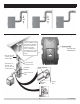
1.
Chimney connector should be kept as short as possible.
Horizontal length of chimney connector should not be
greater than 10 feet.
2.
Type L Vent pipe or other suitable material may be
used for chimney connector if ue temperature is less
than 570° F.
3.
4,5 & 6 section boilers are equipped with a sheet metal
ue collar for attaching 5" diameter chimney connector.
Attach chimney connector to ue collar with 3 standard
sheet metal screws (eld supplied).
4.
7 section boilers are equipped with a cast iron ue
collar for attaching 6" diameter chimney connector.
Attach chimney connector to ue collar using furnished
drill bit to drill holes for furnished screws. Vent
Connection Kit (drill bit and screws) furnished in
accessory carton. Predrill to avoid cracking cast iron
ue collar.
5.
Inspect chimney and connector annually for signs of
debris and corrosion. Loose mortar at base of chimney
may be sign of condensate damage to chimney.
6.
Inspect base of chimney for any signs of seepage.
Discoloration may be a sign of chimney damage. Have
repaired immediately.
7.
Contact qualied service agent immediately to examine
damage and correct. Operation of damaged chimney
may cause venting failure and force ue gases into
living space.
8.
If chimney is to be re-lined, use recommendations in
NFPA31, Appendix E or CSA B139.
14.3 Draft
• Natural draft generated through chimney is dependent
on several factors including, chimney height,
temperature of ue gases, cross section area of
chimney, chimney wall insulation value, dilution air and
total volume of ue gases. Operate boiler for at least 5
minutes before measuring draft.
• Minimum Draft at Breech – Draft induced by the
chimney must create at least a neutral pressure of 0
(zero) inches water column (INWC) at breech. Slightly
negative (i.e. suction) pressure is preferred. Pressure
at breech cannot be positive since this could create
condition that allows ue gas by-products to escape
from draft regulator. Draft is to be measured up stream
of draft regulator. See Burner Specications.
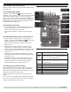
• Over-re Draft - Measure pressure at 1/4” NPT test port.
Three pass boilers have higher pressure drop than single
pass. Table 9 shows expected pressure drop between
over-re and breech. Total pressure drop is difference
between over-re draft and breech draft. For example,
if over-re draft = 0.05 INWC and breech draft = - 0.05,
total pressure drop = 0.05 - (-0.05) = 0.10 INWC. See
Figure 23, Page 25
.
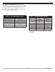
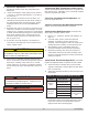
Table 9 - Pressure Drop Between
Over-Fire & Breech
Sections Inches WC
4 0.03-0.05
5 0.05-0.08
6 0.09-0.16
7 0.07-0.16
14.4 Stack Temperature
1.
Higher stack temperature, greater amount of draft
generated. Lower stack temperature not only reduces
amount of draft created but also increases possibility
ue gases could condense in chimney connector or
stack.
2.
Consult NFPA 31 for information for appropriate choice
of venting materials. Chimney may have to be lined to
create sufcient draft, or chimney may have to be lined
to prevent corrosion of masonry chimney. Consult
qualied service agency for chimney requirements in
your area.
3.
Bafes – Efciency of boiler is based on insertion of
ue bafes supplied with 4,5 & 6 section units. Bafes
are installed in 3rd pass (two inner ueways). Refer to
“8 - Boiler Assembly” on page 13 for bafe installation.
Remove bafes to increase stack temperature.
4.
Remove bafes if any signs of condensation in chimney
or chimney connector. Removing bafes may not
address condensation.
14 - CHIMNEY AND VENTING CONNECTIONS
PN 473900000