
Install Instructions

13
WARNING
Burn and scald hazard. Relief valve could
discharge steam or hot water during operation.
Check local codes for maximum distance from oor
or allowable safe point of discharge. Installation of
relief valve shall be consistent with ANSI/ASME Boiler
and Pressure Vessel Code, Section IV.
!
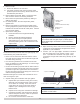
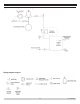
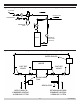
10. Install Relief Valve.
See
Figures 6 and 7
.
A. DO NOT pipe in area where freezing can occur. DO
NOT install shutoff valves, plugs or caps.
B. Locate 3/4”NPT x 90° street elbow. Install elbow using
3/4” NPT tapping in supply piping. Install elbow with
outlet facing directly up. Install relief valve with outlet
facing horizontally.
C. Pipe discharge of relief valve. Installation of relief
valve must be consistent with ANSI/ASME Boiler and
Pressure Vessel Code, Section IV.
Figure 7 - Relief Valve
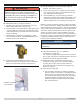
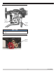
11.
Conrm thermal limit/LWCO sensor bulb is fully
inserted to bottom of control well in top of rear boiler
section and secured with grommet. See Figure 8.
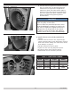
12. Check installation of liners and bafes (Not all
models)
. See Table 4, Page 14.
A. Check oval (4 section) or V-shaped (6 and 7 section)
liner. See
Figures 9 & 10
. Liner should be ush with
front edge of heat exchanger ns.
B. Flue way bafes (4, 5, 6 section only) are factory
installed in 3rd pass. Insure bafes are inserted in ue
way such that position tab touches casting between
2nd and 3rd Pass ue way. See
Figure 11, Page 14.
Efciency of boiler is based on insertion of ue way bafes
in 4, 5 and 6 section units. Bafes will generate lower gross
stack temperatures entering chimney. This has the potential
under certain operating conditions to cool ue gases below
dew point, creating condensation on interior chimney and
chimney connector surfaces. Remove bafes to increase
stack temperature if there are any signs of condensation in
chimney or chimney connector. Removing bafes alone may
not address condensation depending on other boiler and
heating system operating conditions.
NOTICE
Flue gas condensate is corrosive, which requires
special consideration and must be addressed
immediately.
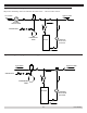
13. Connect Field Wiring.
See “13 - Electrical
Connections” on page 22.
120 volt power supply eld wiring connects to junction
box on right side panel. Provide appropriate overcurrent
protection and service disconnect switch.
14. Install drain valve
. Install drain valve with hose
connection facing right or left. This allows clearance
for swing door to open and close with drain and
hose attached. Verify connection is water tight. See
Figure 13, Page 15.
15. Close burner swing door
.
A. Use one hand to hold door in position by applying
pressure directly to door while re-installing securing
hardware with your opposite hand. Always install
non-hinged side latching hardware rst, then install
hinged side hardware. Apply additional pressure
while hand tightening hardware as far as possible,
then release pressure.
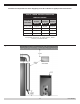
8 - BOILER ASSEMBLY
SENSOR IN WELL
WITH GROMMET
Figure 8 Grommet
PN 473900000