
User Guide

Monitron S2 Boiler Operation and Installation Instructions
DESCRIPTION
The Monitron boiler is a low pressure hot water heating electric boiler. The heat-
ing elements are sheathed resistance type. The heat exchanger is cast-iron. The
heat exchanger is constructed, inspected, and stamped in accordance with
Section IV of the American Society of Mechanical Engineers (ASME) Boiler and
Pressure Vessel Code. In addition, the Monitron Boiler is equipped with a safety
relief valve, operating control and two high limit controls.
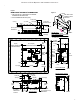
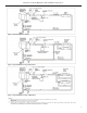
MOUNTING
The Monitron is intended for wall mounting, utilizing the wall brackets attached to
the boiler (see Figure 1). Allow sufficient space for piping and service. The boiler
may be installed in an enclosed space (see Figure 1). The boiler must be
INSTALLED LEVEL.
PIPING
Air Separator and Expansion Tanks
The recommended piping arrangement is shown in figures 3 through 5. Note that
there is a built-in air eliminator in the heat exchanger (air vent, however, is by oth-
ers). The air vent tapping is 13mm (1/2”). A bushing (by others) to suit the size of
the air vent thread is required. Additional air vents should be installed at points
just upstream from all drops in elevation of the piping system (high points).
Relief Valve Discharge Piping
Use same size or larger piping than valve outlet. Must terminate 152mm ( 6”)
minimum from floor with a plain ( no threads) end. Place a bucket under pressure
relief valve discharge. Make sure discharge is always visible. DO NOT hard-pipe
to drain piping.
Flow Switch
THE INSTALLATION OF A FLOW SWITCH IS STRONGLY
RECOMMENDED. It is intended to prevent the burnout of heater elements should
the circulator fail, or should air accumulate in the boiler due to faulty air elimina-
tion (see Table 3 for flow switch size required). FLOW SWITCH MUST BE
INSTALLED IN HORIZONTAL POSITION.
IF A FLOW SWITCH IS NOT USED JUMPER THE “FF” TERMINALS (JUMPER
NOT SUPPLIED.)
Bypass
The bypass shown must be set so that a sufficient amount of water can circulate
through the boiler when all zone valves are closed. (See Figure 4.) A bypass is
mandatory on a constant circulation system using zone valves if a wild loop is not
part of the system. The bypass line will prevent circulator damage caused by a
circulator running up on head.
Multi-zone Balancing
Raise all zone thermostat settings and verify that all zone valves are
open (bypass valve should be closed). Close all electrical panels. Turn
on 15 amp control circuit breaker ONLY. Pump
should operate. Note the pressure reading on the pump discharge.
Lower each zone thermostat setting to close corresponding zone valve.
Adjust the corresponding balancing valve to maintain pump discharge
pressure. The pump discharge pressure should remain the same when
all zones are in bypass or when all zones are open or any combination
of opened and closed. (See Figure 4 & 5.)
WIRING
To wire the electric boiler, perform the following procedures:
1. Wall Thermostat Flow Switch and Circulator
All circuit breakers ahead of boiler must be OFF. Remove the Control
Panel (left-hand front cover) by removing 5 screws from top, bottom and
side flanges. The centre compartment contains a 24V control terminal
board marked, "FF/TT/ (see figure 2 ) Wire a 24V, two-wire heating ther-
mostat or the auxiliary end switch terminals from zone valves (see
Figure 7) to "TT". The "FF" terminals are for a flow switch. Do not con-
nect the wires to the flow switch "FF" terminals until the by-pass flow
adjustments are completed. Refer to "Bypass Flow Adjustment" (page 7)
for wiring and adjustment procedures. The flow switch wires should be
taped at the boiler until they are to be connected to "FF".
The left compartment contains a 120V terminal board marked "A-
B/Circulator". Wire the circulator and connect wires and conduit through
the 13 mm (1/2") knockout (provided on the bottom left hand corner of
the cabinet) to the terminal board "Circulator" terminals. These terminals
supply 120 volts to the circulator only when there is a call for heat.
Wire an external zone valve transformer to the "A-B" terminals if zone
valves are used. These terminals provide a constant 120 volts and can
alternately be used to power the circulator if constant circulation is desir-
able. Use 90°C minimum wire, copper or aluminum.
2. Service Connections and Electrical Ratings
A. All circuit breakers ahead of boiler must be OFF. Remove the
Service Connection Panel (right hand front) cover by removing 5
screws from the top, bottom and side flanges (see wiring diagram
on back of the Service Connection Panel and Figure 2).
B. Draw power feeder cable (75°C minimum) and conduit through
service K.O. provided on side, top or bottom.
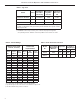
C. Connect hot lines to main lugs on breaker base provided in
service compartment. A ground lead should be drawn and wired
to the ground lug in the service compartment. If rating plate
indicates boiler is a single phase 3-wire or 3-phase 4-wire model,
draw a neutral wire #12 AWG maximum, 75°C minimum and
connect to neutral lug provided in service compartment. See
Tables 1 and 2 for lug sizes and current ratings.
2
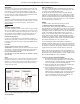
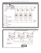
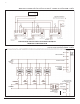
For three phase,
third power leader
lug is added.
TO ZO NE VALVE T R AN S FOR ME R
OR FOR CON STANT C IRCULATOR
OPE RATION WHEN DESIRED
T
YPICAL WIRI NG DIAGRAM
Figure 2. Typical Wiring Diagram for Models equipped with
Circuit Breakers.