
Install Instructions


2 EH-M2-40 Boiler Operation and Installation Instructions
DESCRIPTION
The Monitron II boiler is a low pressure hot water heating electric
boiler. The control is a 4 stage electronic control with energy saving
and other features. The heating elements are sheathed resistance
t
ype. The heat exchanger is cast-iron. The heat exchanger is con-
structed, inspected, and stamped in accordance with Section IV of
t
he American Society of Mechanical Engineers (ASME) Boiler and
Pressure Vessel Code. In addition, the Monitron II Boiler is equipped
w
ith a safety relief valve conforming to ASME requirements and two
separate limit controls conforming to U.L. requirements. The Monitron
II boiler is Underwriters'
Laboratories, Inc. listed.
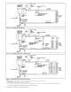
MOUNTING
The Monitron II is intended for wall mounting, utilizing the wall brack-
e
ts attached to the boiler (see Figure 1). Allow sufficient space for
piping and service. The boiler may be installed in an enclosed
space (see Figure 1). The boiler must be INST
ALLED LEVEL.
PIPING
Air Separator and Expansion Tanks
The recommended piping arrangement is shown in Figures 2
through 4. Note that there is a built-in air eliminator in the heat
exchanger (air vent, however, is by others). A 1/8" air vent may be
used. Additional air vents should be installed at points just upstream
from all drops in elevation of the piping system (high points).
Flow Switch
A FLOW SWITCH MUST BE INSTALLED. It is intended to prevent
the burnout of heater elements should the circulator fail, or should air
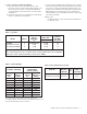
accumulate in the boiler due to faulty air elimination (see Table 3 for
flow switch size required). FLOW SWITCH MUST BE INSTALLED
IN HORIZONTAL POSITION.
Bypass
The bypass shown must be set so that a sufficient amount of water
can circulate through the boiler when all zone valves are closed. See
Figure 3.
Multi-zone Balancing
Raise all zone thermostat settings and verify that all zone valves are
open (not bypassed). Close all electrical panels. Turn on 10 amp
control circuit breaker ONLY. Pump should operate. Note the pres-
sure reading on the pump discharge. Lower each zone thermostat
s
etting to close corresponding zone valve. Adjust the corresponding
balancing valve to maintain pump discharge pressure. The pump dis-
charge pressure should remain the same when all zones are in
bypass or when all zones are open or any combination of opened
a
nd closed. See Figure 4.
WIRING
To wire the electric boiler, perform the following procedures:
1.
Wall Thermostat Flow Switch and Circulator
• All circuit breakers ahead of and at boiler must be OFF.
Remove the Control Panel (left-hand front) Cover by removing
5 screws from top, bottom and side flanges.
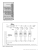
• The right-hand compartment under the Control Panel Cover
contains a terminal board marked, (SLANT/FIN “INTERFACE
BOARD”). Wire a 2-wire 24V room heating thermostat or the
auxiliary end switch terminals of zone valves (see Figure 5) to
terminals 3 and 4 at this time. The 1 and 2 terminals are for the
flow switch. The flow switch circuit is a low voltage circuit.
• Wire the circulator and connect 115V wires and conduit
through 1/2" K.O. provided on bottom left hand corner, to the
“INTERFACE BOARD” at terminals “L” and “N”, where it is
marked “CIRC. PUMP”.