
Brochure


Boiler
Model No.
SINGLE
PHASE
* KW at
240 VAC
SINGLE
PHASE
D.O.E
Capacity
*(Btu/hr) at
240 VAC
Neutral Lug
Size (AWG)
Solid
Cu
Stranded
Cu
SINGLE PHASE –– THREE WIRE
Main Lug
Size (AWG)
CU
Grounding
Lug Size
(AWG)
Cu
† ** Heater
Amps at
240 VAC
THREE PHASE –– FOUR WIRE 120/208 VAC WYE
KW at
208 VAC
D.O.E
Capacity
(Btuh) at
208 VAC
Main Lug
Size (AWG)
CU
Grounding
Lug Size
(AWG)
Cu
† Heater
Amps at
208 VAC
EH-8M3 8 27000 14-12 12 6-2/0 6-2/0 33 ––– ––– ––– ––– –––
EH-10M3 10 34000 14-12 12 6-2/0 6-2/0 42 ––– ––– ––– ––– –––
EH-12M3 12 41000 14-12 12 6-2/0 6-2/0 50 9.012 31000 6-2/0 6-2/0 43.4
EH-16M3 16 55000 14-12 12 6-2/0 6-2/0 67 12.016 41000 6-2/0 6-2/0 ‡57.8
EH-20M3 20 68000 14-12 12 6-2/0 6-2/0 83 15.020 51000 6-2/0 6-2/0 ‡72
EH-24M2 24 82000 14-12 12 6/2/0 6-2/0 100 18.024 62000 6-2/0 6-2/0 ‡69
EH-28M2 28 96000 14-12 12 6-2/0 6-2/0 117 21.028 72000 6-2/0 6-2/0 ‡69
EH-32M2 32 109000 14-12 12 6-2/0 6-2/0 133 24.032 82000 6-2/0 6-2/0 ‡83
EH-40M2 40 137000 14-12 12 2-310 MCM 6-2/0 167 30.040 103000 6-2/0 6-2/0 ‡108.3
* Multiply by 0.751 for values at 208 volts AC.
** Multiply by 0.867 for values at 208 volts AC.
† For total current add, to the value shown in the table, the current draw for
circulator and/or zone valve transformer (10 Amp. max.),
‡ Leg with the highest value of line current of an unbalanced 3 phase load.
“135M2” for single phase, 120V/240V, 120V/208V WYE. 3 wire
(see note (1) below) with control circuit breaker.
“345M2” for three phase, 120V/208V WYE. 4 wire (see note (1)
below) with control circuit breaker.
Example: EH-20-135M2=20KW boiler for 120V/240V.
120V/208V Single Phase 3 wire, with EM-10 boiler control.
Specify Model as follows: Model Number. Single or three Phase.
ELECTRICAL
FOR USE WITH TWO-WAY ZONE VALVES
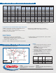
NOTES:
1. Optional blocking gate valve and hose end valve
used (with drain valve) for fast fill and purge of
system.
IMPORTANT Close bypass line valve
(if used) during purging.
2. Alternative circulator location could be installed on
supply piping. Circulator should not be installed at
lowest point of piping.
3. There should be no elbows, tees, or change of
pipe size for at least 5 diameters of pipe size
(see table below) upstream and downstream of
flow switch.
Boiler Model
Flow Switch
McDonnell
& Miller No.
Pipe
Size
Minimum Length of
Straight Pipe Upstream
and Down-Stream
of Flow Switch
EH-40M2 FS8W 1
1
⁄4 IN. 8
1
⁄2 IN.
EH-8M2- EH-32M2 FS4-3T3-1 1 IN. 6
1
⁄2 IN.
EH-8M3- EH-20M3 FS4-3T3-1 1 IN. 6
1
⁄2 IN.
©Slant/Fin Corp. 2011. Printed in U.S.A. 411 Publication EH-M2/M3-10
RATINGS AND SPECIFICATIONS
TYPICAL PIPING DIAGRAM
• Single branch circuit for 3 wire 120/208 V WYE,
120/240 Volt a.c. single phase, 60 Hz or for 4 wire
120/208V WYE three phase, 60Hz a.c. See note (1) below.
• Circulator relay 10 AMP Max, 120V a.c.
Note No. 1: Voltage of any line to ground cannot exceed 125 VAC.
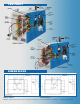
• Heating elements: Low-density replaceable. Copper sheathed
and silver brazed base.
OUTDOOR
SENSOR
AUTO AIR VENT
ABOVE BUILT-IN
COLLECTING
CHAMBER
FLOW SWITCH
(SEE NOTE 3)
RELIEF
VALVE
1
1
⁄4" SUPPLY
TAPPING
ALTERNATE
CIRCULATOR
LOCATION
BOILER
OUTLET
SENSOR
OPTIONAL
AUTO FILL
VALVE
BYPASS
LINE
TO SYSTEM
TRIDICATOR
1
1
⁄4" RETURN
TAPPING
FILL
DIAPHRAGM
COMPRESSION
TANK
THROTTLING
VALVE OR
COCK
FROM SYSTEM
CIRCULATOR
(SEE NOTE 2)
DRAIN
VALVE
(SEE NOTE 1)
U.S.A.
Slant/Fin Corporation • 100 Forest Drive
Greenvale, NY 11548 • 516-484-2600
www.slantfin.com
Canada
Slant/Fin LTD/LTEE • 6450 Northam Drive
Mississauga, Ontario L4V 1H9 • 905-677-8400
www.slantfin.ca
®
BOILERS & BASEBOARD
Since 1949
T
h
e
O
n
l
y
N
a
m
e
Y
o
u
W
a
n
t
H
e
a
t
i
n
g
Y
o
u
r
H
o
m
e
.
Monotron II
Minitron III
1
1
⁄4" RETURN
TAPPING
Monotron II
Minitron III