
User Guide


14
EM-40-SM Service Manual
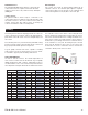
TEST THE POWER SUPPLY
M
ake sure exposed wires are not in contact with other wires
or grounded surfaces. Turn on the power and measure the
v
oltage between the C and R pins using an AC voltmeter, the
reading should be between 22 and 26 V (ac).
TEST THE POWERED INPUTS
Heat Demand
If a heat demand is used, measure the voltage between
the CD (common demand) and the Ht D (heat demand)
pins. When the heat demand device calls for
heat, between 20 and 130 V (ac) should be measured at
the pins
. When the heat demand device is off, less than 5
V (ac) should be measured.
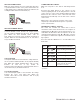
Setpoint Demand
If a setpoint demand is used, measure the voltage between
the CD (common demand) and the Set D (setpoint demand)
pins
.
When the setpoint demand de
vice calls for heat,
between 20 and 130 V (ac) should be
measured at the pins. When the setpoint demand device is
off, less than 5 V (ac) should be measured.
Test the External Input
If an external input signal is used, measure the voltage
between the Com/- and +V(in) pins. When the
e
xter
nal control calls for heat, between 0 and 10 V (dc)
should be measured.
CONNECTING THE CONTROL
M
ake sure all power to the devices and wiring harness
is off.
R
econnect the wiring harness to the connector on the
control by aligning the tab on the wiring harness to the tab
o
n the connector on the control and then pushing the wiring
harness into the connector on the control. The tab on the
w
iring harness should snap over the tab on the connector
of the control.
Apply power to the control. The operation of the control
on power up is described in the Sequence of Operation
section of the brochure.
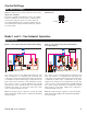
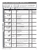
TESTING THE CONTROL OUTPUTS
The control has a built-in test routine that is used to
override the main control functions. The test sequence is
enabled when the
p button is pressed and held for 3 sec-
onds while in the View menu. The test sequence can be can-
celled by pressing either the Item, p or q button. Once the
test sequence is enabled, the outputs are tested in the follow-
ing sequence.
Press and hold the
p button for 3 seconds while in the
View menu.
-5 -21 100,221
0-1885,362
5 -15 72,918
10 -12 62,465
1
5-9 53,658
6
5 18 13,474
70 21 11,883
75 24 10,501
80 27 9,299
85 29 8,250
1
35 57 2,754
140 60 2,490
145 63 2,255
150 66 2,045
155 68 1,857
2
05 96 763
210 99 703
215 102 648
220 104 598
225 107 553
22 to 26 V (ac)
20 to 130 V (ac)
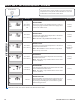
S
tep 1
Boil
T
he boiler pump is turned on.
Step 2
Boil
1
Stage 1 heating element(s) on.
Step 3
Boil
12
Stage 2 heating element(s) on.
Step 4
Boil
123
Stage 3 heating element(s) on.
Step 5
Boil
1234
Stage 4 heating element(s) on.
Step 6
The boiler pump and stages 1
to 4 are shut off. The alert is
closed for 10 seconds.
The control exits the test sequence and resumes normal
operation.
,
-35 -37 280,279
-30 -34 234,196
-
25 -32 196,358
-
20 -29 165,180
-15 -26 139,402
-10 -23 118,018
-5 -21 100,221
0-1885,362
5 -15 72,918
10 -12 62,465
1
5-9 53,658
,
35 2 29,996
40 4 26,099
4
5 7 22,763
5
010 19,900
55 13 17,436
60 16 15,311
6
5 18 13,474
70 21 11,883
75 24 10,501
80 27 9,299
85 29 8,250
,
105 41 5,210
110 43 4,665
1
15 46 4,184
1
20 49 3,760
125 52 3,383
130 54 3,050
1
35 57 2,754
140 60 2,490
145 63 2,255
150 66 2,045
155 68 1,857
,
175 79 1,281
180 82 1,172
1
85 85 1,073
1
90 88 983
195 91 903
200 93 829
2
05 96 763
210 99 703
215 102 648
220 104 598
225 107 553
22 to 26 V (ac)
20 to 130 V (ac)
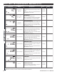
Step 1
Boil
The boiler pump is turned on.
Step 2
Boil
1
Stage 1 heating element(s) on.
Step 3
Boil
12
Stage 2 heating element(s) on.
Step 4
Boil
123
Stage 3 heating element(s) on.
Step 5
Boil
1234
Stage 4 heating element(s) on.
Step 6
The boiler pump and stages 1
to 4 are shut off. The alert is
closed for 10 seconds.
The control exits the test sequence and resumes normal
operation.
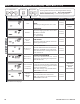
Temperature Resistance
°F °C
-50 -46 490,813
-
45 -43 405,710
-40 -40 336,606
-
35 -37 280,279
-30 -34 234,196
-25 -32 196,358
-20 -29 165,180
-15 -26 139,402
-10 -23 118,018
-5 -21 100,221
0-1885,362
5 -15 72,918
10 -12 62,465
15 -9 53,658
Temperature Resistance
°F °C
20 -7 46,218
2
5-4 39,913
30 -1 34,558
3
52 29,996
40 4 26,099
45 7 22,763
50 10 19,900
55 13 17,436
60 16 15,311
65 18 13,474
70 21 11,883
75 24 10,501
80 27 9,299
85 29 8,250
Temperature Resistance
°F °C
90 32 7,334
9
5 35 6,532
100 38 5,828
1
05 41 5,210
110 43 4,665
115 46 4,184
120 49 3,760
125 52 3,383
130 54 3,050
135 57 2,754
140 60 2,490
145 63 2,255
150 66 2,045
155 68 1,857
Temperature Resistance
°F °C
160 71 1,689
1
65 74 1,538
170 77 1,403
1
75 79 1,281
180 82 1,172
185 85 1,073
190 88 983
195 91 903
200 93 829
205 96 763
210 99 703
215 102 648
220 104 598
225 107 553
22 to 26 V (ac)
20 to 130 V (ac)
Step 1
Boil
The boiler pump is turned on.
Step 2
Boil
1
Stage 1 heating element(s) on.
Step 3
Boil
12
Stage 2 heating element(s) on.
Step 4
Boil
123
Stage 3 heating element(s) on.
Step 5
Boil
1234
Stage 4 heating element(s) on.
Step 6
The boiler pump and stages 1
to 4 are shut off. The alert is
closed for 10 seconds.
The control exits the test sequence and resumes normal
operation.