
User Guide


13
EM-40-SM Service Manual
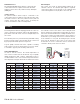
DHW Tank Sensor
A
n optional DHW Tank Sensor may be connected to the
control. If the sensor is required, connect the two wires
f
rom the sensor to the Com (common sensor) and Sys/D
(DHW) pins.
Outdoor Sensor
An optional Outdoor Sensor may be connected to the
control. If the sensor is required, connect the two wires from
t
he Outdoor Sensor to the Com (common sensor) and Out
(outdoor sensor) pins. The outdoor sensor is used by the
control to measure the outdoor air temperature.
External Input
T
he control can accept an external input signal from an
external control. If an external input signal is required,
c
onnect the positive 0-10 V (dc) wire to the +V(in) pin and
connect the negative 0-10 V (dc) wire to the Com/- pin.
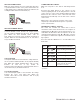
The wiring harness must be unplugged from the connector
on the control before testing. To remove the wiring harness,
push down on the tab on the connector and pull away from
the control.
The following tests are performed using standard testing
practices and procedures and should only be carried out
by properly trained and experienced persons.
A good quality electrical test meter, capable of reading
from at least 0-300 V (ac) and at least 0-2,000,000 Ohms,
is essential to properly test the wiring and sensors.
TEST THE SENSORS
In order to test the sensors, the actual temperature at
each sensor location must be measured. A good quality
digital thermometer with a surface temperature probe is
recommended for ease of use and accuracy. First measure
the temperature using the thermometer and then measure
the resistance of the sensor at the control. Using the chart
below, estimate the temperature measured by the sensor.
The sensor and the thermometer readings should be close.
If the meter reads a very high resistance, there may be a
broken wire, a poor wiring connection or a defective sensor.
If the resistance is very low, the wiring may be shorted,
there may be moisture in the sensor or the sensor may
be defective. To test for a defective sensor, measure the
resistance directly at the sensor location.
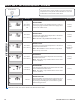
Testing
Outdoor
Sensor
Temperature Resistance
°F °C
-50 -46 490,813
-45 -43 405,710
-40 -40 336,606
-35 -37 280,279
-30 -34 234,196
-25 -32 196,358
-20 -29 165,180
-15 -26 139,402
-10 -23 118,018
-5 -21 100,221
0-1885,362
5 -15 72,918
10 -12 62,465
15 -9 53,658
Temperature Resistance
°F °C
20 -7 46,218
25 -4 39,913
30 -1 34,558
35 2 29,996
40 4 26,099
45 7 22,763
50 10 19,900
55 13 17,436
60 16 15,311
65 18 13,474
70 21 11,883
75 24 10,501
80 27 9,299
85 29 8,250
Temperature Resistance
°F °C
90 32 7,334
95 35 6,532
100 38 5,828
105 41 5,210
110 43 4,665
115 46 4,184
120 49 3,760
125 52 3,383
130 54 3,050
135 57 2,754
140 60 2,490
145 63 2,255
150 66 2,045
155 68 1,857
Temperature Resistance
°F °C
160 71 1,689
165 74 1,538
170 77 1,403
175 79 1,281
180 82 1,172
185 85 1,073
190 88 983
195 91 903
200 93 829
205 96 763
210 99 703
215 102 648
220 104 598
225 107 553
2
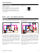
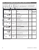
Step 1
Boil
The boiler pump is turned on.
Step 2
Boil
1
Stage 1 heating element(s) on.
S