
Install Instructions


EH-M2-40 Boiler Operation and Installation Instructions 3
Table 1. Lug Sizes
SINGLE PHASE 3 WIRE THREE PHASE, 4 WIRE
120/208V, 120/240V‡ 120/208V-WYE
CIRCUIT ONL
Y‡
Basic Heater Basic Heater
Model Amperes* Model Amperes†
No. @240V No. @208V
EH-8-M2 33
EH-10-M2 42
EH-12-M2 50 EH-12-M2 43
EH-16-M2 67 EH-16-M2 58†
EH-20-M2 83 EH-20-M2 72†
EH-24-M2
100
EH-24-M2 69†
EH-28-M2 117 EH-28-M2 69†
EH-32-M2 133 EH-32-M2 83†
EH-40-M2 167 EH-40-M2 108†
Table 2. Current Ratings
* For current values @ 208V, multiply current @ 240V by 0.867.
† Leg with the highest v
alue of line current of an unbalanced 3-phase load.
‡ 125 VAC maximum rating of all hot conductors.
Table 3. Flow Switch Size Selection
*
Str
aight pipe upstream and do
wnstream
2. Service Connections and Electrical Ratings
A. All circuit breakers ahead of and at boiler must be OFF.
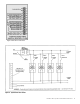
Remove the Service Connection Panel (right hand front). Cover
by removing 5 screws from the top, bottom and side flanges
(see wiring diagram on back of the Service Connection Panel
and Figure 5).
B
. Draw power feeder cable (75°C minimum) and conduit through
service K.O. provided on top and bottom.
C
. Connect hot lines to distribution block provided in service compart-
ment. A ground lead should be drawn and wired to the ground lug
in the service compartment. If rating plate indicates boiler is a sin-
gle phase 3-wire or 3-phase 4-wire model, draw a neutral wire #12
AWG maximum, 75˚C. minimum and connect to neutral din rail
mount provided in service compartment. See Tables 1 and 2 for lug
s
izes and current ratings.
3. Wiring Control
• See EM-10 Electronic Control Set Up Instructions #790860000
f
or setting up control.
Model No.
Flow Switch
McDonnell
& Miller No.
Pipe
Size
Pipe
Length of
Flow Switch
EH-40-M2
EH-8-M2 thru EH-32-M2
FS8W
FS4-3T3-1
1-1/4"
1"
8-1/2”
6-1/2”
Model Phase
Distribution
Block
Wire Siz
e
CU
Grounding Lug
Wire Size
Neutral
Din Rail
Mount-CU
CU
EH-40-M2
EH-8-M2 thr
u 32
-M2
EH-12-M2 thr
u 40
-M2
1
1
3
2-3/0 MCM CU
6-2/0
6-2/0
6-2/0
6-2/0
6-2/0
12
12
12
Neutral Lug Wire Size:
The neutral tap is for the circulator and control transformer. The maximum
wire size of the neutral should not exceed 12 AWG.