
User Guide


Multi/Pak
®
93 & 95
INSTALLATION INSTRUCTIONS
Use the following table for recommended number of bracket-hanger
assemblies for each piece of enclosure and accessory.
ENCLOSURE NUMBER OF BRACKETS
LENGTH BRACKET-HANGERS ONLY
Up to 5' 2 –
6' Through 8' 3 –
ACCESSORIES
Valve cover, inside – 2
Corner, Outside corner
TELESCOPIC
ACCESSORIES:
DAMPER:
These accessories telescope up to 2" of
total length dimension. Wall to wall
dimension, figured at job site, is not
affected.
When specified, the damper is factory
installed except the damper knob and
lead screw assembly. See instructions
below
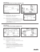
OPTIONAL DAMPER KNOB & LEAD SCREW ASSEMBLY
INSTRUCTIONS
1. Screw LEAD SCREW into LEAD SCREW NUT about halfway, the
unthreaded end towards the BUSHING in the TOP COVER.
2. Line up LEAD SCREW with BUSHING HOLE by sliding DAMPER
right or left.
3. Swing DAMPER towards rear of TOP COVER (away from
BUSHING) and guide LEAD SCREW through BUSHING HOLE
until stop on LEAD SCREW is against BUSHING and unthreaded
part of LEAD SCREW protrudes through front of TOP COVER.
4. Place KNOB onto LEAD SCREW and line up allen head SET
SCREW in KNOB with flat LEAD SCREW and tighten SET
SCREW with an allen wrench.
Slant/Fin Corporation, 100 Forest Drive
Greenvale, New York 11548 • Phone: 516-484-2600
www.slantfin.com
Printed in U.S.A. 703
Part No. 294006
Publication No. 93/95-40