
Overview of Primary Product

H
-1 1
3
⁄4"
copper 3" x 3
1
⁄4"
x .024" aluminum 48 1079 486 572 658 745 848 928 1025 1133
H
-3 1
3
⁄4"
copper 2
3
⁄4"
x 2
1
⁄2"
x .011" aluminum 55 991 446 525 605 684 773 852 941 1041
9
3
⁄4” H-4 1 1" copper 3" x 2
1
⁄2" x .011" aluminum 48 965 434 511 589 666 753 830 917 1013
H-5X 1 1
1
⁄4" copper 3" x 3
1
⁄4" x .020" aluminum 48 1030 464 546 628 711 803 886 979 1082
H
-6X 1 1
1
⁄4"
IPS Steel 3" x 3
1
⁄4"
x .028" aluminized steel 48 883 397 468 539 609 689 759 839 927
E
-75 1
3
⁄4"
copper 2
5
⁄16"
x 2
1
⁄8"
aluminum 55 828 373 439 505 571 646 712 787 869
H-1 1
3
⁄4" copper 3" x 3
1
⁄4" x .024" aluminum 48 1182 532 626 721 816 922 1017 1123 1241
H
-3 1
3
⁄4"
copper 2
3
⁄4"
x 2
1
⁄2"
x .011" aluminum 55 1086 489 576 662 749 847 934 1032 1140
1
6
3
⁄4”
H-4 1 1" copper 3" x 2
1
⁄2"
x .011" alumin
um 48 1057 476 560 645 729 824 909 1004 1110
H
-5X 1 1
1
⁄4"
copper 3" x 3
1
⁄4"
x .020" aluminum 48 1128 508 598 688 778 880 970 1072 1184
H
-6X 1 1
1
⁄4"
IPS Steel 3" x 3
1
⁄4"
x .028" aluminized steel 48 947 426 502 578 653 739 814 900 994
E-75 1
3
⁄4" copper 2
5
⁄16" x 2
1
⁄8" aluminum 55 907 408 481 553 626 707 780 862 952
H
-1 2
3
⁄4"
copper 3" x 3
1
⁄4"
x .024" aluminum 48 1679 756 890 1024 1159 1310 1444 1595 1763
H-3 2
3
⁄4" copper 2
3
⁄4" x 2
1
⁄2" x .011" aluminum 55 1543 694 818 941 1065 1204 1327 1466 1620
16
3
⁄4” H-4 2 1" copper 3" x 2
1
⁄2" x .011" aluminum 48 1501 675 796 916 1036 1171 1291 1426 1576
H-5X 2 1
1
⁄4" copper 3" x 3
1
⁄4" x .020" aluminum 48 1602 721 849 977 1105 1250 1378 1522 1682
H-6X 2 1
1
⁄4"IPS Steel 3" x 3
1
⁄4" x .028" aluminized steel 48 1435 646 761 875 990 1119 1234 1363 1507
E-75 2
3
⁄4" copper 2
5
⁄16" x 2
1
⁄8" aluminum 55 1288 580 683 786 889 1005 1108 1224 1352
9
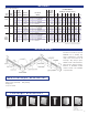
C
over
Type
Enclosure
Height
Element
Type
Rows
of
H
eating
Elements
T
ube Size
and Material
F
in Size and
Material
Fins
P
er
Foot
9
3-10
93-17
93-17
Two-tier
element
Steam
1
PSI*
B
tu/Hr.
P
er Foot
H
OT WATER RATINGS*
BTU/HR./FT. (Flow Rate 3 Ft./Sec.)
F
or ratings at lower water temperatures, refer to conversion table on page 33.
*
Based on 65
0
F
entering air temperature.
w
ith or without dampers
End Cap Splice plate Filler sleeve Center valve cover Inside corner, 90
o
Outside corner, 90
o
End valve cover,
End Cap-slotted slotted, 10"
(not shown) End valve cover, 10"
(not shown)
Column co
ver set Tamper-proof lock
Damper (electro galvanized)* Wall gasketing*
Hanging str
ip*
*See p
.5 for details
RATINGS
ACCESSORIES
telescopic accessories
non-telescopic accessories
Fourteen accessories let you “fit”
Multi/Pak 93 in virtually any
space configuration – fast and
easily. Cover accessories are all
telescopic. They snap in place
without screws or other fasteners.
All accessories, unless noted, are
finished in Nu-White baked
enamel. Custom color available
on special order.
150˚ F 160˚F 170˚F 180˚F 190˚F 200˚F 210˚F 220˚F
Access doors: 6” x 6”